
User manual


XLP 8-Bit Development Board User’s Guide
DS41581A-page 26 2011 Microchip Technology Inc.
3.2.7 User-Defined LEDs
The board features seven green LEDs [D8 – D1] (RA5, RB5, RB4, RE7, RE6, RE5 and
RE4) that can serve as user-defined outputs. The LEDs are not used in the demonstra-
tion software and, by default, jumper J27 is unpopulated, preventing the LEDs use.
3.2.8 Potentiometer
A 100 kΩ potentiometer (R9) is connected to AN3 for both MCU devices. It can be
adjusted from V
DD to VSS to provide an analog input voltage to the A/D Converter.
The potentiometer functions to show the full capable range of the temperature display.
Its functionality is dependent upon J19 and J20 configuration.
3.2.9 16x2 Character LCD with Controller and Backlight
The board includes the NHD‐C0216CZ‐FSW‐FBW‐3V3 from Newhaven Display Inter-
national. The screen features the ability to write 2 lines x 16 characters, runs at 3 V
DD
with a 3V backlight display supported by two side White LEDs used for backlight.
3.2.10 Serial EEPROM
A 24AA256 256 KB (32 Kbytes x 8) serial EEPROM (U1) is connected to SPI for both
the PIC16(L)F1947 64-pin and PIC18F87K22 80-pin devices. It is used to demonstrate
SPI bus operation. It is included for nonvolatile firmware storage, in addition to the inter-
nal data EEPROM of the PIC16 and PIC18 devices.
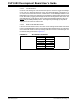
3.2.11 Modular Expansion Connector
The XLP 8-bit board implements a 28-pin modular expansion interface (J21).
This modular expansion is in place to allow use with some PICtail™ interface available
on many Microchip demo and development boards. It may not implement the full range
of signals supported by some PICtail interfaces; the connector pin assignments for J21
are shown in Appendix 1. “Development Board Schematics”. It is recommended
users reference the schematic before using a PICtail™ expansion on the board. This
additional modular expansion allows the user to incorporate other Microchip demo
boards or all expansion of peripheral features through use of the expansion interface.
3.2.12 Serial Accessory Port
The XLP 8-bit board supports the expansion and use of a serial connection. The SAP
supports the outputs of (TX, V
DD, GND, SDA, SCL, RX) from the SAP header (J2).
Through the use of SW4 and J4/J5 the user has the ability to output a signal which can
be recognized through UART, SAP, or I
2
C™. The type of communication is dependent
upon the SAP PROTOCOL switch (S1).
3.2.13 Temperature Sensor
The MCP9700 Low-Power Linear Active Thermistor IC supports a range of -40°C to
+125°C and operates between the range of 2.3V and 5.5V, consuming typically 6 uA
current when active. The temperature sensor’s output is read by the MCU through pin
RA3 if jumper J20 is set to pins [2-3].
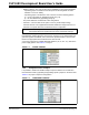
3.2.14 Generous Prototyping Area
To assist in the development and testing of application hardware, the XLP board
includes a 24 x 11 prototype area for the installation of the user’s custom circuitry.
Sources for the board power V
DD and ground are located above the area. Supplied
from 19 different I/O signals, the prototyping area supplies a wide range of possible fea-
tures which can be tested and experimented with from the prototyping area.