
User manual


XLP 8-BIT DEVELOPMENT BOARD
USER’S GUIDE
2011 Microchip Technology Inc. DS41581A-page 23
Chapter 3. XLP 8-Bit Development Board Hardware
3.1 INTRODUCTION
This chapter provides a more detailed description of the hardware features of the XLP
8-Bit Development Board.
3.2 HARDWARE FEATURES
The key features of the XLP 8-bit board are listed below. They are represented in the
order given in Section 1.4 “Development Board Features” and Figure 1-1.
3.2.1 64 and 80 PIC MCU Support
The XLP 8-bit board has been designed to accommodate PIC16 and PIC18 microcon-
trollers through a Plug-In Module (PIM) containing the microcontroller. A wide variety
of 64 and 80-pin microcontroller devices are available on Plug-In Modules through
Microchip. It is recommended to check all PIM breakout schematics to the XLP sche-
matics to compare for functionality and feature set.
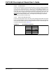
3.2.1.1 FEATURES AVAILABILITY BY PIC16 AND PIC18 DEVICE FAMILY
The high degree of pin compatibility between PIC16 and PIC18 MCU devices allows
both device families to be used with the XLP 8-bit board. However, there are minor dif-
ferences in pin functionality when migrating from a 64-pin device to a 80-pin device
requiring reconfiguration of the board and some features of the board are not available
for 64-pin devices.
3.2.2 PIC16 and PIC18 Oscillator Options
The installed microcontroller has two separate oscillator circuits connected. An external
oscillator of 10 MHz crystal (Y1) is supplied on board but is not used in the demonstra-
tion program. The MCU uses the internal system oscillator in the demonstration pro-
gram. A second oscillator, using a 32.768 kHz crystal (Y2), functions as the Timer1
oscillator and serves as the source for the RTCC and secondary oscillator.
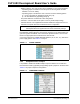
3.2.3 Power Options
There are (4) methods by which the 8-bit XLP board can be powered.
• USB Cable – Bus power via the USB connector (J11). This provides a nominal 5V
power source, regulated to approximately 3.3V for the microcontroller and board
components, through a Schottky diode and Low Dropout (LDO) regulator circuit
(U2). The green power LED (D5) is illuminated when this power source is used
and bus power is present.
• External Power – An external, regulated DC power supply connected to the V
DD
SRC and one of the GND test points. Voltage is supplied to the board and micro-
controller without voltage drops or voltage regulation; therefore, supply voltage
must meet the voltage requirements for the installed PIC16 or PIC18 device. The
power LED does not illuminate in this configuration.
Note: There is no USB data connectivity.