
User manual


XLP 8-Bit Development Board User’s Guide
DS41581A-page 18 2011 Microchip Technology Inc.
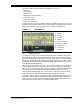
The button layout to set the clock is also displayed on the screen. The clock will display
either a 12-hour or 24-hour time scale, depending upon the custom preferences. If no
preferences are set, the software default is a 24-hour time scale. After setting the clock,
the Real Time Clock Counter (RTCC) will be initialized, enabling and using Timer1,
which keeps count of time using the on-board 32 kHz oscillator crystal. The screen will
display the main menu for two seconds. The program is now at the “8-Bit XLP Main
Menu”.
To navigate the menus, the M
CLR button function is [Up], the RB0 button function is
[Down] and the RB1 button function is [Select]. The RB1 button is also the only button
accepted as an interrupt while in SLEEP(). RB1 is used to enter and exit all three
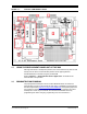
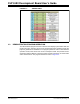
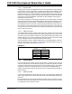
modes [Active, Conserve, Sleep]. The button layout is shown in Figure 2-3.
FIGURE 2-3: BUTTONS LAYOUT
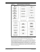
2.2.1 8-Bit XLP Main Menu
From the main menu location the user has four selections: Active mode, Conserve
mode, Sleep mode and Settings menu.
2.2.1.1 ACTIVE MODE
In Active mode the CPU and peripherals features are on. The peripherals are still
dependent upon software-based enables. In this case, the only peripherals active are
the ADC used in connection with the temperature sensor or on-board POT; Timer1
used for the RTCC; Timer2 and CCP2, both used to control backlight brightness
through the use of the Pulse-Width Modulator (PWM). All other peripheral features
have been disabled through the INTCON, PIR and PIE registers.
A – Select
B – Up
C – Down
Note 1: B is sometimes used to increment hours.
2: C is sometimes used to increment minutes
3: Holding either B or C down will increment values gradually.
Note: On the PIC18 device, the PMD registers are also referenced.