
User manual


XLP 8-BIT DEVELOPMENT BOARD
USER’S GUIDE
2011 Microchip Technology Inc. DS41581A-page 15
Chapter 2. The XLP Demonstration Application
This chapter describes the demonstration application that is preprogrammed on the
PIC18F87K22 microcontroller. It can also be applied to the demonstration program for
the PIC16(L)F1947 supplied on the XLP web site. The demonstration program will
show the use of low-power techniques in a working application. In the process, the
application highlights various features of these two microcontroller families.
2.1 INITIAL SETUP
Although intended as a development platform, the XLP 8-bit board is also designed to
be used directly from the box as a demonstration platform. The demonstration firmware
preprogrammed in the PIC18F87K22 microcontroller PIM is ready for immediate use.
The supplied PIC16(L)F1947 microcontroller PIM needs to be programmed with the
code supplied on the XLP web site.
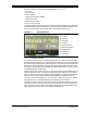
The demonstration firmware uses the on-board LCD to report temperature and timing
information while the push buttons select between modes of operation.
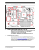
2.1.1 Configuring and Connecting the Hardware
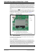
To get started with the board, verify that it is properly configured:
1. Verify the PIM is correctly installed into socket J1. The notch on the edge of the
PIM should be aligned with the matching print on the board.
2. Verify that SW4 is set to the correct setting as indicated on the board, for the cor-
responding PIM used.
3. Populate the power source select jumper for USBPWR, J11.
4. Populate the jumpers for VBOARD, J16 and VMCU, J15.
5. Populate the jumper for POT EN, J19. Choose the selection jumper for J20,
either VPOT [1-2] or VTEMP [2-3]. J20 can be moved between selections
mid-program to explore both options.
6. Populate SAP I
2
C pull-ups, J4 and J5. Although not used in the demonstration
program, these allow future expansion through the Serial Accessory Port (SAP),
J2.
7. Populate INT2, J23. Leave INT0, J25 and INT1, J24 unpopulated.
8. Connect the development board to the PC with the provided USB cable (A to
mini-B). The board will not enumerate, but will source power from the USB port.
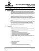
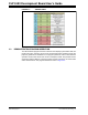
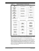
The default jumper configuration table is shown in Figure 2-1.