XLP 8-Bit Development Board User’s Guide 2011 Microchip Technology Inc.
Note the following details of the code protection feature on Microchip devices: • Microchip products meet the specification contained in their particular Microchip Data Sheet. • Microchip believes that its family of products is one of the most secure families of its kind on the market today, when used in the intended manner and under normal conditions. • There are dishonest and possibly illegal methods used to breach the code protection feature.
XLP 8-BIT DEVELOPMENT BOARD USER’S GUIDE Table of Contents Chapter 1. Introduction to the XLP 8-Bit Board 1.1 Introduction ................................................................................................... 11 1.2 Highlights ...................................................................................................... 11 1.3 What’s in the Box ......................................................................................... 12 1.4 Development Board Features ...................
XLP 8-Bit Development Board User’s Guide NOTES: DS41581A-page 4 2011 Microchip Technology Inc.
XLP 8-BIT DEVELOPMENT BOARD USER’S GUIDE Preface NOTICE TO CUSTOMERS All documentation becomes dated, and this manual is no exception. Microchip tools and documentation are constantly evolving to meet customer needs, so some actual dialogs and/or tool descriptions may differ from those in this document. Please refer to our web site (www.microchip.com) to obtain the latest documentation available. Documents are identified with a “DS” number.
XLP 8-Bit Development Board User’s Guide CONVENTIONS USED IN THIS GUIDE This manual uses the following documentation conventions: DOCUMENTATION CONVENTIONS Description Arial font: Italic characters Represents Referenced books Emphasized text A window A dialog A menu selection A field name in a window or dialog A menu path MPLAB® IDE User’s Guide ...is the only compiler...
Preface WARRANTY REGISTRATION Please complete the enclosed Warranty Registration Card and mail it promptly. Sending in the Warranty Registration Card entitles users to receive new product updates. Interim software releases are available at the Microchip web site. RECOMMENDED READING This user’s guide describes how to use XLP 8-Bit Development Board. Other useful documents are listed below. The following Microchip documents are available and recommended as supplemental reference resources.
XLP 8-Bit Development Board User’s Guide THE MICROCHIP WEB SITE Microchip provides online support via our web site at www.microchip.com. This web site is used as a means to make files and information easily available to customers.
Preface CUSTOMER SUPPORT Users of Microchip products can receive assistance through several channels: • • • • Distributor or Representative Local Sales Office Field Application Engineer (FAE) Technical Support Customers should contact their distributor, representative or Field Application Engineer (FAE) for support. Local sales offices are also available to help customers. A listing of sales offices and locations is included in the back of this document.
XLP 8-Bit Development Board User’s Guide NOTES: DS41581A-page 10 2011 Microchip Technology Inc.
XLP 8-BIT DEVELOPMENT BOARD USER’S GUIDE Chapter 1. Introduction to the XLP 8-Bit Board 1.1 INTRODUCTION Thank you for purchasing Microchip Technology’s XLP 8-Bit Development Board. The board provides a low-cost, highly configurable development system for Microchip’s new line of 64 and 80-pin Extreme Low-Power (XLP) microcontrollers, including the PIC16(L)F1947 and PIC18F87K22 families.
XLP 8-Bit Development Board User’s Guide 1.3 WHAT’S IN THE BOX The XLP 8-Bit Development Board includes the following: • • • • • 1.4 XLP 8-Bit Development Board PIC16(L)F1947 Plug-In Module PIC18F87K22 Plug-In Module USB mini-B cable Power Analyzer cable DEVELOPMENT BOARD FEATURES A layout of the XLP 8-Bit Development Board is shown in Figure 1-1. The board includes these specific features, as indicated in the diagram: 1. Connector for Plug-In Modules (PIM) 2. Oscillator circuits (10 MHz and 32.
FIGURE 1-1: 1.5 8-BIT XLP COMPONENT LAYOUT USING THE DEVELOPMENT BOARD OUT OF THE BOX Although intended as a development platform, the XLP 8-bit board may also be used directly from the box as a demonstration platform for the preprogrammed PIC18F87K22 microcontroller using the provided PIM. Refer to Chapter 2. “The XLP Demonstration Application” for details on the demonstration code operation. 1.
XLP 8-Bit Development Board User’s Guide NOTES: DS41581A-page 14 2011 Microchip Technology Inc.
XLP 8-BIT DEVELOPMENT BOARD USER’S GUIDE Chapter 2. The XLP Demonstration Application This chapter describes the demonstration application that is preprogrammed on the PIC18F87K22 microcontroller. It can also be applied to the demonstration program for the PIC16(L)F1947 supplied on the XLP web site. The demonstration program will show the use of low-power techniques in a working application. In the process, the application highlights various features of these two microcontroller families. 2.
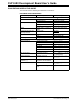
XLP 8-Bit Development Board User’s Guide FIGURE 2-1: 2.2 JUMPER TABLE DEMONSTRATION PROGRAM OPERATION The demonstration program uses the on-board LCD to display system status data, temperature and time. The time can be set for the Real-Time Clock operation and be displayed in global time or AM/PM time. The program permits the user to select between operation modes, each with its own current consumption values.
FIGURE 2-2: DEMO APPLICATION SOFTWARE FLOW On power-up, the PIC® device will first run through its initialize process. First, it will set the device’s system clock to be configured for the custom set frequency. If no custom preferences are set, the device will be set to the program default of 4 MHz. Next, the program will run through the Low_Power()routine, where the devices I/O ports are configured for their ideal low-current use settings. All unused interrupts are disabled.
XLP 8-Bit Development Board User’s Guide The button layout to set the clock is also displayed on the screen. The clock will display either a 12-hour or 24-hour time scale, depending upon the custom preferences. If no preferences are set, the software default is a 24-hour time scale. After setting the clock, the Real Time Clock Counter (RTCC) will be initialized, enabling and using Timer1, which keeps count of time using the on-board 32 kHz oscillator crystal.
The active display shows the following as displayed in Figure 2-4: • • • • • • • clock time time standard alarm indicator brightness percentage (PWM) temperature value temperature standard system clock frequency To escape Active mode the user has the option to press RB1 (Select) at any time. The user also has the option to escape Active mode if the alarm is enabled and the specified time is met. Upon exiting, the user will return to the “8-Bit XLP Main Menu”.
XLP 8-Bit Development Board User’s Guide 2.2.1.3 SLEEP MODE In Sleep mode, the CPU and peripherals are off. In this Power-Saving mode the device is fully asleep. The only events which can wake it from Sleep are the Watchdog Timer (WDT), Brown-out Reset (BOR), Secondary Oscillator SOSC, RTCC, ULPWU and I/O-based interrupts. In our demonstration program the WDT and BOR have been disabled in the configuration (fuses).
Under clock standard, the user has the option to toggle between [24-hour] and [12-hour] time. If [12-hour] is selected, it should reflect an accurate representation of [24-hour] time using an ‘A’ or ‘P’ display to indicated morning or evening time. By choosing Set Alarm, the user will have the option to choose a 30 or 60 minute nap timer or to set a custom alarm time.
XLP 8-Bit Development Board User’s Guide 2.2.2.4 LCD SETTINGS Under the LCD settings the user will have the option to choose to toggle the backlight for the LCD or to adjust its brightness. If the user selects Backlight, it will toggle on or off. If the user chooses Save Custom, it will store the current Backlight status into the EEPROM for the custom user preferences. By default the demonstration program is set to ON. Note that by toggling the backlight off will reset the brightness value.
XLP 8-BIT DEVELOPMENT BOARD USER’S GUIDE Chapter 3. XLP 8-Bit Development Board Hardware 3.1 INTRODUCTION This chapter provides a more detailed description of the hardware features of the XLP 8-Bit Development Board. 3.2 HARDWARE FEATURES The key features of the XLP 8-bit board are listed below. They are represented in the order given in Section 1.4 “Development Board Features” and Figure 1-1. 3.2.
XLP 8-Bit Development Board User’s Guide • Battery Powered – The user has two options available for using external batteries. - Populating jumper J9 allows the user the option of selecting either two AAA batteries or a 3V coin battery. - Populating jumper J12 allows the user to choose one of the following options: a) one 3V coin battery by populating jumper pins [1-2] b) two AAA batteries by populating pins [2-3]. The power LED does not illuminate in this configuration.
• J4 – Population of this jumper enables the pull-up resistor for the PIC16(L)F1947 SDA line, RD5, supplied to the Serial Accessory Port (SAP). Dependent upon hardware switch (SW4). • J5 – Population of this jumper enables the pull-up resistor for the PIC18F87K22 SDA line, RD1, supplied to the Serial Accessory Port (SAP). Dependent upon hardware switch (SW4). • J15 – Population of this jumper disables the ability to take current measurements from the MCU.
XLP 8-Bit Development Board User’s Guide 3.2.7 User-Defined LEDs The board features seven green LEDs [D8 – D1] (RA5, RB5, RB4, RE7, RE6, RE5 and RE4) that can serve as user-defined outputs. The LEDs are not used in the demonstration software and, by default, jumper J27 is unpopulated, preventing the LEDs use. 3.2.8 Potentiometer A 100 kΩ potentiometer (R9) is connected to AN3 for both MCU devices. It can be adjusted from VDD to VSS to provide an analog input voltage to the A/D Converter.
3.2.15 Programming Interfaces The PICkit header (J3) can be used by either the PICkit™ 2 or PICkit™ 3 programming devices. Through use of the PICkit 3 the user is capable of debugging the included demonstration software or creating and debugging custom software in use with the 8-bit XLP. 3.3 CURRENT MEASUREMENT An advantage to the XLP 8-bit board is its provisions for in-circuit current measurement.
XLP 8-Bit Development Board User’s Guide NOTES: DS41581A-page 28 2011 Microchip Technology Inc.
XLP 8-BIT DEVELOPMENT BOARD USER’S GUIDE Appendix 1. Development Board Schematics The following schematic diagrams are included in this appendix: • • • • Figure 1-1: PIC16LF1947 PIM Breakout Figure 1-2: PIC18F87K22 PIM Breakout Figure 1-3: Schematic for XLP Development Board (1 of 2) Figure 1-4: Schematic for XLP Development Board (2 of 2) 2011 Microchip Technology Inc.
XLP 8-Bit Development Board User’s Guide FIGURE 1-1: DS41581A-page 30 PIC16LF1947 PIM BREAKOUT 2011 Microchip Technology Inc.
FIGURE 1-2: PIC18F87K22 PIM BREAKOUT 2011 Microchip Technology Inc.
XLP 8-Bit Development Board User’s Guide FIGURE 1-3: DS41581A-page 32 SCHEMATIC FOR XLP DEVELOPMENT BOARD (1 OF 2) 2011 Microchip Technology Inc.
FIGURE 1-4: SCHEMATIC FOR XLP DEVELOPMENT BOARD (2 OF 2) 2011 Microchip Technology Inc.
XLP 8-Bit Development Board User’s Guide NOTES: DS41581A-page 34 2011 Microchip Technology Inc.
XLP 8-BIT DEVELOPMENT BOARD USER’S GUIDE Index Numerics P 2x16 Character LCD ................................................ 12 32 kHz LFINTOSC ................................................... 21 4 MHz HFINTOSC ................................................... 21 500 kHz MFINTOSC ................................................ 21 8-Bit XLP Main Menu ............................................... 18 Connector for Plug-In Modules (PIM)....................... 12 Conserve Mode........................
XLP 8-Bit Development Board User’s Guide W Warranty Registration................................................. 7 Watchdog Timer (WDT) ........................................... 20 WWW Address ........................................................... 8 DS41581A-page 36 2011 Microchip Technology Inc.
XLP 8-Bit Development Board User’s Guide NOTES: 2011 Microchip Technology Inc.
Worldwide Sales and Service AMERICAS ASIA/PACIFIC ASIA/PACIFIC EUROPE Corporate Office 2355 West Chandler Blvd. Chandler, AZ 85224-6199 Tel: 480-792-7200 Fax: 480-792-7277 Technical Support: http://www.microchip.com/ support Web Address: www.microchip.