
User manual


MPLAB STARTER KIT FOR PIC24F
USER’S GUIDE
© 2008 Microchip Technology Inc. DS51725A-page 31
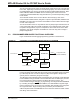
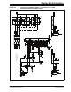
Appendix A. Starter Kit Schematics
The following schematic diagrams are included in this appendix:
Programmer/Debugger:
• Figure A-1: Programmer/Debugger Control System and EEPROM
• Figure A-2: Programmer/Debugger USB Interface, Target Power Switching and
Regulation
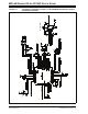
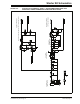
Application:
• Figure A-3: Application Microcontroller, Touch Switches and Associated
Components
• Figure A-4: OLED Display, LED and Application Side USB Connectors