
User manual


Hardware
© 2008 Microchip Technology Inc. DS51725A-page 29
5.3 BOARD COMPONENTS
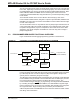
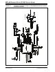
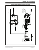
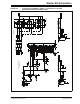
Figure 5-3 identifies the key hardware components for the starter kit.
FIGURE 5-3: PIC24F STARTER KIT COMPONENT LAYOUT
TABLE 5-1: PIC24F STARTER KIT COMPONENT DESCRIPTIONS
5.3.1 Programmer/Debugger Components
The components listed here (in order of their reference tags in Figure 5-3) are the key
components of the programmer/debugger side of the starter kit:
D1. mini-B USB Receptacle (J1): Provides system power and bidirectional
communication between the host PC and starter kit.
D2. PIC18F67J50 Microcontroller (U2): Controls the programming/debugging
operations of the target PIC24FJ256GB106 microcontroller. It also provides the
12 MHz clock for the PIC24F microcontroller.
D3. MCP1727 Voltage Regulator (U1): The 3.3V linear regulator regulates the USB
unregulated voltage to 3.3 volts (with respect to V
SS) and supplies the starter kit
with system power.
D4. Target Power LED (D4): When lit, indicates that power is being supplied to the
application side of the starter kit from V
BUS (either from a USB connection or from
the V
BUS test point).
Ref Debug/Programmer Component Ref Application Component
D1 mini-B USB Receptacle (J1) A1 PIC24F256GB106 Microcontroller (U6)
D2 PIC18F67J50 Microcontroller (U2) A2 Tri-Color LED Pads (D6, D10 or D11)
D3 MCP1727 Voltage Regulator (U1) A3 OLED Display (LED1)
D4 Target Power LED (D4) A4 Capacitive Touch Pad (S1)
D5 Low V
CE Saturation PNP Transistor Switch (Q1) A5 32.768 kHz (RTCC) Crystal (Y2)
D6 Debugger/Programmer Clock Crystal (Y1) A6 USB A (Embedded Host) Receptacle (J4)
D7 25LC010A Serial EEPROM (U3) A7 mini-B USB (Peripheral) Receptacle (J5)
D8 V
BUS and GND Test Points A8 Potentiometer (R44)
D9 System Power LED (D2) A9 OLED Voltage Boost Cicuitry
D10 Debug LED (D3)
M
D2
D3 D4
D6
D7
A1
A2
A4
A5
A6
A8
A9
D5
D1
D8
D9
A3
A7
D10