
User manual


Configuring the Starter Kit Hardware
© 2008 Microchip Technology Inc. DS51725A-page 17
3.2.4 Embedded Host, Release Mode (Stand-Alone Mode)
In this configuration, the starter kit has been programmed with a debugged,
stand-alone USB embedded host application; programmer/debugger support is not
needed. Because of the absence of a host PC, this configuration can truly be
considered a “stand-alone” operation.
Since there are no connections to a host PC, the starter kit board must be physically
modified to accept an external power supply. A regulated power supply providing 5 V
DC
must be available.
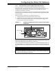
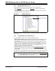
Make the following modifications to the starter kit (Figure 3-3):
1. Install posts at the V
BUS and GND test points on the board.
2. Populate the site for R16 (adjacent to the V
BUS test point) with a 0 ohm resistor.
3. Supply +5 V
DC and ground connections from the external power supply to the
V
BUS and GND connections on the board.
FIGURE 3-3: STARTER KIT MODIFICATIONS FOR STAND-ALONE POWER
OPERATION
If the modifications are done correctly, and power is connected correctly, the green
Target Power LED (D4) is lit. The starter kit also goes through its power-on sequence
before LED1 displays the “PIC24 Starter Kit” main menu.
When configured for external power operation, the programmer/debugger function is
essentially disabled. To re-enable these functions, disconnect the external power from
the board and remove the resistor/jumper from R16 before connecting the USB cable
to J1.
M
Ground
+5.0V
R16 (populate)
CAUTION
If you externally power VBUS via the test point, please make certain that you first
disconnect any USB cables connected to a computer or hub. Otherwise, damage to the
PC’s USB port or the external hub may result.