
User manual

MPLAB Starter Kit for PIC24F User’s Guide
DS51725A-page 16 © 2008 Microchip Technology Inc.
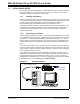
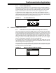
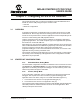
FIGURE 3-1: STARTER KIT SETUP (DEVICE, DEBUG MODE)
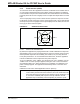
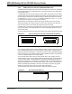
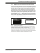
3.2.3 Device, Release Mode
In this configuration, the starter kit has been programmed with a debugged,
stand-alone USB device application; programmer/debugger support is not needed.
The only connection required is a USB cable between J5 and the host PC (Figure 3-2).
The cable provides both power and data connection to the host side application,
making it a bus-powered application.
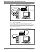
FIGURE 3-2: STARTER KIT SETUP (DEVICE, DEBUG MODE)
A to mini-B (Programmer)
Starter Kit
M
A to mini-B (Application)
1
2
Starter Kit
M
A to mini-B (Application)