
User manual

The Demonstration Application
© 2008 Microchip Technology Inc. DS51725A-page 11
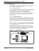
2.1.3 Time and Date (RTCC)
The PIC24F microcontroller has an on-chip Real-Time Clock and Calendar (RTCC)
module that the application uses to provide a continuous display of the date and time
(in 24-hour format) on the main menu. As the starter kit does not have an on-board
battery, the date and time must be set each time power is applied to the board.
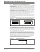
To set the RTCC, select “Utilities” from the main menu, then “Date/Time” from the
“Utilities” menu. Use the left/right arrow keys to scroll between fields; the border of the
selected field becomes bolded. Use the up/down keys to set the value. When finished,
press the center touch pad to return directly to the main menu.
FIGURE 2-3: SET DATE/TIME DISPLAY
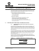
2.2 SPECIFIC DEMO HIGHLIGHTS
2.2.1 RGB LED Control (Three PWMs and Peripheral Pin Select)
Three of the PIC24F microcontroller’s PWM modules control the three-color LED (D6),
and can be adjusted to control the LED’s brightness and color. To provide more current
to the LED channels and increase brightness, each channel is tied to two of the micro-
controller’s output pins. The Peripheral Pin Select feature of PIC24F devices allows
users to map the output of a single module (in this case, a PWM) to more than one pin,
avoiding any issues of coordinating separate pins in the process. The use of multiple
pins for a single PWM is transparent to the rest of the application.
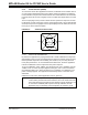
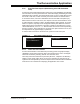
To access this feature, select “Demos” from the Main display, then “RGB LED” from the
“Demonstrations menu”. The LED lights up at this point. By default, all three colors are
set at their brightness midpoint (Figure 2-4).
Use the up/down touch pads to select a color component, and the left/right touch pads
to adjust that color’s intensity. When finished, press the center touch pad to extinguish
the LED and return to the main display.
FIGURE 2-4: DEFAULT RGB LED CONTROL DISPLAY
Set Date/Time
i
+
-
Nov
+
-
01
+
-
2007
+
-
10
+
-
01
RGB LED
i
Red
Blue
Green