MPLAB Starter Kit for PIC24F User’s Guide © 2008 Microchip Technology Inc.
Note the following details of the code protection feature on Microchip devices: • Microchip products meet the specification contained in their particular Microchip Data Sheet. • Microchip believes that its family of products is one of the most secure families of its kind on the market today, when used in the intended manner and under normal conditions. • There are dishonest and possibly illegal methods used to breach the code protection feature.
MPLAB STARTER KIT FOR PIC24F USER’S GUIDE Table of Contents Preface ........................................................................................................................... 1 Chapter 1. Introduction to the Starter Kit 1.1 Overview ........................................................................................................ 7 1.2 Operational Requirements ............................................................................. 7 1.3 Initial Board Setup .....................
MPLAB Starter Kit for PIC24F User’s Guide NOTES: DS51725A-page iv © 2008 Microchip Technology Inc.
MPLAB STARTER KIT FOR PIC24F USER’S GUIDE Preface NOTICE TO CUSTOMERS All documentation becomes dated, and this manual is no exception. Microchip tools and documentation are constantly evolving to meet customer needs, so some actual dialogs and/or tool descriptions may differ from those in this document. Please refer to our web site (www.microchip.com) to obtain the latest documentation available. Documents are identified with a “DS” number.
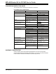
MPLAB Starter Kit for PIC24F User’s Guide CONVENTIONS USED IN THIS GUIDE This manual uses the following documentation conventions: DOCUMENTATION CONVENTIONS Description Arial font: Italic characters Represents Examples Referenced books Emphasized text A window A dialog A menu selection A field name in a window or dialog A menu path MPLAB® IDE User’s Guide ...is the only compiler...
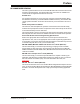
Preface RECOMMENDED READING This user’s guide describes how to use the MPLAB Starter Kit for PIC24F. Other useful documents are listed below. The following Microchip documents are available and recommended as supplemental reference resources. Readme Files For the latest information on using other tools, read the tool-specific Readme files in the Readmes subdirectory of the MPLAB IDE installation directory.
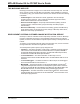
MPLAB Starter Kit for PIC24F User’s Guide THE MICROCHIP WEB SITE Microchip provides online support via our web site at www.microchip.com. This web site is used as a means to make files and information easily available to customers.
Preface CUSTOMER SUPPORT Users of Microchip products can receive assistance through several channels: • • • • Distributor or Representative Local Sales Office Field Application Engineer (FAE) Technical Support Customers should contact their distributor, representative or field application engineer (FAE) for support. Local sales offices are also available to help customers. A listing of sales offices and locations is included in the back of this document.
MPLAB Starter Kit for PIC24F User’s Guide NOTES: DS51725A-page 6 © 2008 Microchip Technology Inc.
MPLAB STARTER KIT FOR PIC24F USER’S GUIDE Chapter 1. Introduction to the Starter Kit Thank you for purchasing Microchip Technology’s MPLAB Starter Kit for PIC24F. This board is intended to introduce and demonstrate the capabilities and features of PIC24F microcontrollers. In addition, the starter kit has on-board in-circuit debug circuitry so that you may develop and debug your own applications. This chapter introduces the starter kit and provides an overview of its features.
MPLAB Starter Kit for PIC24F User’s Guide 1.3 INITIAL BOARD SETUP With its pre-installed demo application, the MPLAB Starter Kit for PIC24F is designed to be used straight out of the box. Except for a single connection to a computer, no additional hardware or configuration is necessary. 1.3.1 Installing the Software Before connecting the starter kit to any computer for the first time, it is very important to install the accompanying software on the MPLAB Starter Kit for PIC24F CD first.
MPLAB STARTER KIT FOR PIC24F USER’S GUIDE Chapter 2. The Demonstration Application This chapter describes the demonstration application that is preprogrammed on the PIC24F microcontroller, and how various features highlight the device’s processing power and hardware functionality.
MPLAB Starter Kit for PIC24F User’s Guide 2.1.2 Touch Interface (CMTU) To control most of the demo application’s features, the PIC24F microcontroller uses an on-chip Charge Time Measurement Unit (CTMU) module to implement a capacitive touch-sensitive touch pad on the starter kit board. The CTMU allows the microcontroller to directly sense the touch of a fingertip on the touch pad and interpret this as a control input.
The Demonstration Application 2.1.3 Time and Date (RTCC) The PIC24F microcontroller has an on-chip Real-Time Clock and Calendar (RTCC) module that the application uses to provide a continuous display of the date and time (in 24-hour format) on the main menu. As the starter kit does not have an on-board battery, the date and time must be set each time power is applied to the board. To set the RTCC, select “Utilities” from the main menu, then “Date/Time” from the “Utilities” menu.
MPLAB Starter Kit for PIC24F User’s Guide 2.2.2 USB Flash Drive Interface (USB Embedded Host) This demo shows the ability of the PIC24F microcontroller to function as an embedded host by reading data from a USB Flash drive. To access the demo, select “Flash Drive” from the main menu. If a USB Flash drive with files is plugged in to the USB A-receptacle (J4), the display shows the drive volume name and top level file structure in a list box (Figure 2-5).
The Demonstration Application 2.2.4 Real-Time Data Capture (Multitasking with USB Embedded Host) An extension of the Data Graphing demo shows many of the capabilities of the PIC24F microcontroller, all running at the same time: interactive display, multitasking and USB embedded host functionality. This feature allows users not only to graph data and view the results in real time, but also accurately record the results to an external device.
MPLAB Starter Kit for PIC24F User’s Guide NOTES: DS51725A-page 14 © 2008 Microchip Technology Inc.
MPLAB STARTER KIT FOR PIC24F USER’S GUIDE Chapter 3. Configuring the Starter Kit Hardware This chapter discusses how to configure the hardware of the MPLAB Starter Kit for PIC24F for various USB prototypes. Topics covered include: • Overview • Starter Kit Configurations 3.1 OVERVIEW In its default configuration, the application side of the starter kit functions as a USB embedded host.
MPLAB Starter Kit for PIC24F User’s Guide FIGURE 3-1: STARTER KIT SETUP (DEVICE, DEBUG MODE) Starter Kit 1 A to mini-B (Programmer) M 2 A to mini-B (Application) 3.2.3 Device, Release Mode In this configuration, the starter kit has been programmed with a debugged, stand-alone USB device application; programmer/debugger support is not needed. The only connection required is a USB cable between J5 and the host PC (Figure 3-2).
Configuring the Starter Kit Hardware 3.2.4 Embedded Host, Release Mode (Stand-Alone Mode) In this configuration, the starter kit has been programmed with a debugged, stand-alone USB embedded host application; programmer/debugger support is not needed. Because of the absence of a host PC, this configuration can truly be considered a “stand-alone” operation. Since there are no connections to a host PC, the starter kit board must be physically modified to accept an external power supply.
MPLAB Starter Kit for PIC24F User’s Guide NOTES: DS51725A-page 18 © 2008 Microchip Technology Inc.
MPLAB STARTER KIT FOR PIC24F USER’S GUIDE Chapter 4. Developing an Application The MPLAB Starter Kit for PIC24F may be used with MPLAB® IDE, the free intergrated development environment available on Microchip’s web site. MPLAB IDE allows the starter kit to be used as an in-circuit debugger as well as a programmer for the featured device. In-circuit debugging allows you to run, examine and modify your program for the device embedded in the starter kit hardware.
MPLAB Starter Kit for PIC24F User’s Guide 4.1 SETTING UP AN EXAMPLE APPLICATION FOR DEBUG The MPLAB IDE software that is installed on your PC by the starter kit CD-ROM automatically opens an example application that you may use to examine debug features of the starter kit. To prepare the application for debug: 1. Launch MPLAB IDE. The example application project and related workspace will open.
Developing an Application 4.2 RUNNING THE EXAMPLE APPLICATION The starter kit executes in either real time (Run) or steps (Step Into, Step Over, Animate.) Real-time execution occurs when you select Run in MPLAB IDE. Once the device code is halted, either by Halt or a breakpoint, you can step.
MPLAB Starter Kit for PIC24F User’s Guide 4.3.1 Editing Application Code To view application code so it may be edited, do one of the following: • Select Edit>New to create new code or Edit>Open to search for and open an existing code file. • Double-click on a file in the Project window to open an existing code file. See an example Project window in Figure 4-2. FIGURE 4-2: EXAMPLE PROJECT Existing Code File For more information on using the editor to create and edit code, see MPLAB IDE Editor Help. 4.
Developing an Application FIGURE 4-3: 4.3.3 EXAMPLE BREAKPOINT Using Watch Windows To use a Watch window: 1. The Watch window is made visible on the desktop by selecting View>Watch. It contains four selectable watch views (via tabs) in which to view variables (SFRs, symbols and absolute addresses). 2. Select an SFR or symbol from the list and click the related Add button to add it to the Watch window, or click in the “Address” column and enter an absolute address.
MPLAB Starter Kit for PIC24F User’s Guide 4.4 PROGRAMMING THE DEBUGGED APPLICATION When the program is successfully debugged and running, the next step is to program the device for stand-alone operation in the finished design. When doing this, the resources reserved for debug are released for use by the application. To program the application, use the following steps: 1. Disable starter kits as a debug tool by selecting Debugger>Select Tool>None. 2.
Developing an Application 4.8 TROUBLESHOOTING Debug Connection Problems While using the starter kit as a debugger, you may get the error “Unable to Enter Debug Mode” when programming the device. This can result from communication being lost between the starter kit and MPLAB IDE. To resolve this: 1. Unplug the USB cable from the starter kit. 2. Plug the USB cable back into the starter kit. MPLAB IDE should automatically reconnect to the starter kit. If this does not work, do the following: 1.
MPLAB Starter Kit for PIC24F User’s Guide NOTES: DS51725A-page 26 © 2008 Microchip Technology Inc.
MPLAB STARTER KIT FOR PIC24F USER’S GUIDE Chapter 5. Hardware This chapter provides a functional overview of the MPLAB Starter Kit for PIC24F, and identifies the major hardware components. Topics covered include: • Application Functional Overview • Programmer/Debugger Functional Overview • Board Components 5.
MPLAB Starter Kit for PIC24F User’s Guide The microcontroller directly drives the OLED display (LED1) and the tri-color LED (D6, D10 or D11, depending on the board’s manufacturing option). The microcontroller uses the Parallel Master Port to drive the OLED through the PMD7:PMD0 data lines, while PMA0, PMCS2, PMRD and PMWR serve as control signals. A DC boost circuit comprised of power MOSFET Q4, along with D5 and L3, provides the operating voltage for the OLED.
Hardware 5.3 BOARD COMPONENTS Figure 5-3 identifies the key hardware components for the starter kit.
MPLAB Starter Kit for PIC24F User’s Guide D5. Low VCE Saturation PNP Transistor Switch (Q1): Provides target power (via high-side switching) to the application side components via control by the PIC18F67J50. D6. Debugger/Programmer Clock Crystal (Y1): Provides an accurate 12 MHz frequency reference for the PIC18F67J50 microcontroller for stable USB operations in Programming and Debugging modes. The PIC18F67J50 also uses this to generate a second 12 MHz clock for use by the PIC24FJ256GB106 microcontroller.
MPLAB STARTER KIT FOR PIC24F USER’S GUIDE Appendix A. Starter Kit Schematics The following schematic diagrams are included in this appendix: Programmer/Debugger: • Figure A-1: Programmer/Debugger Control System and EEPROM • Figure A-2: Programmer/Debugger USB Interface, Target Power Switching and Regulation Application: • Figure A-3: Application Microcontroller, Touch Switches and Associated Components • Figure A-4: OLED Display, LED and Application Side USB Connectors © 2008 Microchip Technology Inc.
MPLAB Starter Kit for PIC24F User’s Guide STARTER KIT SCHEMATIC, SHEET 1: PROGRAMMER/DEBUGGER CONTROL SYSTEM AND EEPROM Debug Serial EEPROM FIGURE A-1: DS51725A-page 32 © 2008 Microchip Technology Inc.
USB Interface (Bus Powered) 3.3 V LDO Linear Regulator © 2008 Microchip Technology Inc. Host MCU Switchable 3.
MPLAB Starter Kit for PIC24F User’s Guide STARTER KIT SCHEMATIC, SHEET 3: APPLICATION MICROCONTROLLER, TOUCH SWITCHES AND ASSOCIATED COMPONENTS Data Logging FIGURE A-3: DS51725A-page 34 © 2008 Microchip Technology Inc.
Starter Kit Schematics * (128 x 64) Organic LED Display RGB LED * Manufacturing option STARTER KIT SCHEMATIC, SHEET 4: OLED DISPLAY, LED AND APPLICATION SIDE USB CONNECTORS * FIGURE A-4: © 2008 Microchip Technology Inc.
MPLAB Starter Kit for PIC24F User’s Guide NOTES: DS51725A-page 36 © 2008 Microchip Technology Inc.
MPLAB STARTER KIT FOR PIC24F USER’S GUIDE Index B E Block Diagrams Starter Kit Application Side ......................................... 27 Programmer/Debugger Side...................... 28 Board Components Capacitive Touch Pad....................................... 30 Debug LED ....................................................... 30 Debugger/Programmer Clock Crystal ............... 30 mini-B USB Connector.................................29, 30 OLED Display ...........................................
WORLDWIDE SALES AND SERVICE AMERICAS ASIA/PACIFIC ASIA/PACIFIC EUROPE Corporate Office 2355 West Chandler Blvd. Chandler, AZ 85224-6199 Tel: 480-792-7200 Fax: 480-792-7277 Technical Support: http://support.microchip.com Web Address: www.microchip.