
User manual

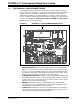


Introduction to the PICDEM.net 2 Development Board
2011 Microchip Technology Inc. DS51623D-page 13
5. OPTIONAL EXTERNAL LCD CONNECTOR: Space is provided on the board for
the installation of a 30-pin, bottom contact FFC edge connector (Hirose
FH12-30S-0.5SH or equivalent). This will allow the use of an external LCD
character display module (such as one of the Optrex™ F-51320 series) to the
board via a ribbon cable. Note that using an external LCD module will require
appropriate changes to the application code, as well as the use of a ribbon cable
compatible with the connector.
6. TEMPERATURE SENSOR: This analog temperature sensor, a Microchip
TC1047 (U1), is connected to an analog I/O pin of the microcontroller. It can be
disconnected by a jumper.
7. USER-DEFINED LEDs: Eight LEDs are driven by digital I/O pins of the controller
(PORTJ) and may be used to simulate a digital output to an embedded device.
They may also be enabled or disabled by jumper selection on the board.
8. USER-DEFINED PUSH BUTTONS: These switches are connected to digital I/O
pins on the microcontroller (PORTB<3:0>) and may be used to simulate a digital
input in an embedded application.
9. USER-DEFINED POTENTIOMETER: One 10 kOhm potentiometer is connected
to an analog I/O pin of the microcontroller. It can be used to simulate an analog
input in an embedded application.
10. RESET PUSH BUTTON: This switch is tied to the MCLR
pin on the controller,
and is used to reset the board.
11. RJ-45 (10Base-T) MODULAR CONNECTORS: The PICDEM.net 2
Development Board is outfitted with two Integrated Connector Modules (ICMs),
one each for the PIC18F97J60 and ENC28J60. These ICMs provide the modu-
lar jack, as well as the necessary transformers, EMI suppression and status
LEDs, for Ethernet connectivity.
Each ICM has its own ACTIVITY and LINK LEDs on the left and right sides of the
ICM. These show if an Ethernet application is transmitting or receiving a packet,
and if the Ethernet connection is active. The LEDs for the PIC18F97J60 (on J1)
can be disconnected by jumpers if the I/O ports, RA0 and RA1, are to be used
for another purpose.
12. RJ-11 (SIX-WIRE) MODULAR CONNECTOR: This allows the Development
Board to be connected to Microchip MPLAB
®
ICD 2, MPLAB ICD 3 or MPLAB
REAL ICE™ in-circuit emulator for in-system programming, as well as advanced
application debugging.
13. SERIAL PORT: The PICDEM.net 2 Development Board includes an RS-232 port
with a DB9 connector (P1) and appropriate level-shifting hardware (U5). This can
be used for debugging or application development purposes, as needed.
14. I/O AND PICtail™ DAUGHTER BOARD ACCESS: A pair of female risers (J5
and J6) allow direct access to five of the microcontroller’s I/O ports (PORTA
through PORTE). The even pins of J5 also serve as a standard interface between
the PICDEM.net 2 Development Board and Microchip’s PICtail daughter board
series.
15. PROTOTYPE AREA: A 9x20 grid with through-holes is provided for users to
breadboard additional circuitry for development. Three SOT-23 pads and a
SOIC-28 footprint are also provided for surface mounting common components.
Connections are provided for +3.3 V
DC, +5 VDC, +9 VDC and ground.
16. ON-BOARD POWER: Two on-board regulators provide separate 5 V
DC and
3.3 V
DC at 500 mA common current from the 9 VDC supplied at J7.
17. POWER-ON LED: This LED (D9) shows the board is powered up.