
User manual


PICDEM™ 2 Plus User’s Guide
DS51275D-page 8 © 2007 Microchip Technology Inc.
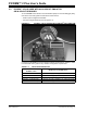
1.3 PICDEM™ 2 PLUS DEMONSTRATION BOARD
The PICDEM 2 Plus demonstration board has the following hardware features:
• 18, 28 and 40-pin DIP sockets
(although three sockets are provided, only one device may be used at a time)
• On-board, +5V regulator for direct input from 9V, 100 mA AC/DC wall adapter or
9V battery, or hooks for a +5V, 100 mA regulated DC supply
• RS-232 socket and associated hardware for direct connection to an RS-232
interface
• In-Circuit Debugger (ICD) connector
•5 kΩ pot for devices with analog inputs
• Three pushbutton switches for external stimulus and Reset
• Green power-on indicator LED
• Four red LEDs connected to PORTB
• Jumper J6 to disconnect LEDs from PORTB
• 4 MHz, canned crystal oscillator
• Unpopulated holes provided for crystal connection
• 32.768 kHz crystal for Timer1 clock operation
• Jumper J7 to disconnect on-board RC oscillator (approximately 2 MHz)
• 32K x 8 Serial EEPROM
• LCD display
• Piezo buzzer
• Prototype area for user hardware
• Microchip TC74 thermal sensor