PICDEM™ 2 Plus Demonstration Board User’s Guide © 2007 Microchip Technology Inc.
Note the following details of the code protection feature on Microchip devices: • Microchip products meet the specification contained in their particular Microchip Data Sheet. • Microchip believes that its family of products is one of the most secure families of its kind on the market today, when used in the intended manner and under normal conditions. • There are dishonest and possibly illegal methods used to breach the code protection feature.
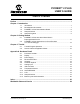
PICDEM™ 2 PLUS USER’S GUIDE Table of Contents Preface ........................................................................................................................... 1 Chapter 1. Introduction 1.1 1.2 1.3 1.4 1.5 Introduction ............................................................................................... 7 Development Kit Contents ........................................................................ 7 PICDEM™ 2 Plus Demonstration Board .........................................
PICDEM™ 2 Plus User’s Guide NOTES: DS51275D-page iv © 2007 Microchip Technology Inc.
PICDEM™ 2 PLUS USER’S GUIDE Preface NOTICE TO CUSTOMERS All documentation becomes dated, and this manual is no exception. Microchip tools and documentation are constantly evolving to meet customer needs, so some actual dialogs and/or tool descriptions may differ from those in this document. Please refer to our web site (www.microchip.com) to obtain the latest documentation available. Documents are identified with a “DS” number. This number is located on the bottom of each page, in front of the page number.
PICDEM™ 2 Plus User’s Guide CONVENTIONS USED IN THIS GUIDE This manual uses the following documentation conventions: DOCUMENTATION CONVENTIONS Description Arial font: Italic characters Initial caps Quotes Underlined, italic text with right angle bracket Bold characters N‘Rnnnn Text in angle brackets < > Courier New font: Plain Courier New Represents Referenced books Emphasized text A window A dialog A menu selection A field name in a window or dialog A menu path MPLAB® IDE User’s Guide ...
WARRANTY REGISTRATION Please complete the enclosed Warranty Registration Card and mail it promptly. Sending in the Warranty Registration Card entitles users to receive new product updates. Interim software releases are available at the Microchip web site. RECOMMENDED READING This user’s guide describes how to use the PICDEM 2 Plus demonstration board. The following Microchip documents are available and recommended as supplemental reference resources.
PICDEM™ 2 Plus User’s Guide THE MICROCHIP WEB SITE Microchip provides online support via our web site at www.microchip.com. This web site is used as a means to make files and information easily available to customers.
CUSTOMER SUPPORT Users of Microchip products can receive assistance through several channels: • • • • Distributor or Representative Local Sales Office Field Application Engineer (FAE) Technical Support Customers should contact their distributor, representative or field application engineer (FAE) for support. Local sales offices are also available to help customers. A listing of sales offices and locations is included in the back of this document.
PICDEM™ 2 Plus User’s Guide NOTES: DS51275D-page 6 © 2007 Microchip Technology Inc.
PICDEM™ 2 PLUS USER’S GUIDE Chapter 1. Introduction 1.1 INTRODUCTION Thank you for purchasing the PICDEM™ 2 Plus demonstration board from Microchip Technology Incorporated. The PICDEM 2 Plus is a simple board that demonstrates the capabilities of the 18, 28 and 40-pin PIC16 and PIC18 devices. The PICDEM 2 Plus can be used stand-alone with a programmed part, with an in-circuit emulator (for example, MPLAB® ICE) or with an in-circuit debugger (such as MPLAB ICD 2).
PICDEM™ 2 Plus User’s Guide 1.
Introduction FIGURE 1-1: PICDEM™ 2 PLUS HARDWARE 7 2 9 8 15 13 11 10 3 5 14 12 4 17 18 1 16 6 1.4 2 SAMPLE DEVICES Two Flash devices are included. The device types may change, but will generally include PIC16 and PIC18 40-pin, DIP devices. 1.5 SAMPLE PROGRAMS The PICDEM 2 Plus kit includes a CD-ROM with sample demonstration programs. These programs may be used with the included sample devices, with an In-Circuit Emulator (ICE) or with an In-Circuit Debugger (ICD).
PICDEM™ 2 Plus User’s Guide NOTES: DS51275D-page 10 © 2007 Microchip Technology Inc.
PICDEM™ 2 PLUS USER’S GUIDE Chapter 2. Getting Started The PICDEM 2 Plus may be used as a stand-alone board with a preprogrammed device, with an In-Circuit Emulator (ICE) or with an In-Circuit Debugger (ICD). For a list of PIC® microcontroller compatible ICEs or ICDs, see the Development Systems Ordering Guide. 2.
PICDEM™ 2 Plus User’s Guide 2.2 PICDEM™ 2 PLUS USED WITH AN IN-CIRCUIT EMULATOR OR IN-CIRCUIT DEBUGGER To use PICDEM 2 Plus with an In-Circuit Emulator (ICE) or In-Circuit Debugger (ICD), refer to the tool’s user guide for instructions to learn how to: • Power-up and configure the ICE/ICD • Connect to target boards (such as in Figure 2-1) PICDEM™ 2 PLUS CONNECTED TO MPLAB® ICD 2 USING USB FIGURE 2-1: Configure the PICDEM 2 Plus for the desired oscillator as described in Table 2-1.
PICDEM™ 2 PLUS USER’S GUIDE Chapter 3. Tutorial The tutorial program is preprogrammed into the sample device. (For example, the file p16demo.hex is for a PIC16 device and p18demo.hex is for a PIC18 device.) This program also is on the included CD-ROM program disk for user reference. (If the sample device has been reprogrammed with another program, the tutorial may be reprogrammed into the device.) For a flowchart of the tutorial program, see Figure 3-1.
PICDEM™ 2 Plus User’s Guide 4. Clock Once this mode is entered from the main menu, a Real-Time Clock will start counting from 00:00:00. The Timer1 module and a 32 kHz clock crystal are used to establish a Real-Time Clock. By pressing RA4, the clock time can be set to the user’s preference. When RA4 is pressed to set the time, the cursor will flash over the hours’ ten digit. Press RA4 again and the cursor will now flash over the minutes’ ten digit.
Tutorial FIGURE 3-1: TUTORIAL PROGRAM FLOWCHART Power-up PICDEM™ 2 Plus Voltmeter RA4 = Next RB0 = Now Volts = 0.33V RB0 = Exit Buzzer RA4 = Next RB0 = Now Prd = 128 DC = 128 RA4 = -> RB0 = ++ Temperature RA4 = Next RB0 = Now RA4 = 3 Presses Temp = 022°C RB0 = Exit Clock RA4 = Next RB0 = Now 00.00.02 RA4 = Set RB0 = Menu 00.00.03 RA4 = -> RB0 = ++ RA4 = 3 Presses © 2007 Microchip Technology Inc.
PICDEM™ 2 Plus User’s Guide 3.2 SOURCE CODE AND APPLICATION NOTES In addition to the assembled tutorial program (hex files), source code used to create these hex files is included on the PICDEM 2 Plus CD-ROM. Both source code and related hex files are found in device-specific directories. Application notes with additional use examples are included on the CD-ROM. For information on how to reprogram the device with new or modified code, or how to restore the tutorial program, please see Section 2.
PICDEM™ 2 PLUS USER’S GUIDE Appendix A. Hardware Detail The PICDEM 2 Plus hardware is extremely simple and illustrates the ease of use of various PIC MCUs. This section describes the PICDEM 2 Plus hardware elements. A.1 PROCESSOR SOCKETS Although three sockets are provided, only one device may be used at a time. • 18-pin socket • 28-pin socket • 40-pin socket A.2 DISPLAY • Four red LEDs are connected to PORTB of each processor type. The PORTB pins are set high to light the LEDs.
PICDEM™ 2 Plus User’s Guide A.5 SWITCHES Three switches provide the following functions: • S1 – MCLR to hard reset the processor • S2 – Active-low switch connected to RA4 • S3 – Active-low switch connected to RB0 Switches, S1 and S3, have debounce capacitors, whereas S2 does not, allowing the user to investigate debounce techniques. When pressed, the switches are grounded. When Idle, they are pulled high (+5V). A.6 OSCILLATOR OPTIONS • RC oscillator (2 MHz approximately) supplied.
Hardware Detail A.12 SAMPLE DEVICES A sample part programmed with a simple program is included in the PICDEM 2 Plus kit. Table A-1 lists the I/O features and port connections for each processor type.
PICDEM™ 2 Plus User’s Guide A.13 BOARD LAYOUT AND SCHEMATICS The following figures show the parts layout (silkscreen) and schematics for the PICDEM 2 Plus demonstration board.
Hardware Detail FIGURE A-2: PICDEM™ 2 PLUS SCHEMATIC © 2007 Microchip Technology Inc.
PICDEM™ 2 Plus User’s Guide PICDEM™ 2 PLUS SCHEMATIC (CONTINUED) PICtail™ Daughter Board FIGURE A-3: DS51275D-page 22 © 2007 Microchip Technology Inc.
PICDEM™ 2 PLUS USER’S GUIDE Index A O A/D Input ...............................................................8, 18 Oscillator Options..................................................... 18 Oscillator Selection .................................................. 12 B Buzzer ...................................................................... 13 Buzzer, Piezo ............................................................. 8 C Clock .......................................................................
WORLDWIDE SALES AND SERVICE AMERICAS ASIA/PACIFIC ASIA/PACIFIC EUROPE Corporate Office 2355 West Chandler Blvd. Chandler, AZ 85224-6199 Tel: 480-792-7200 Fax: 480-792-7277 Technical Support: http://support.microchip.com Web Address: www.microchip.