
User's Manual


Table Of Contents
Evaluating CY920 Board
2014 Microchip Technology Inc. Preliminary DS50002260B-page 19
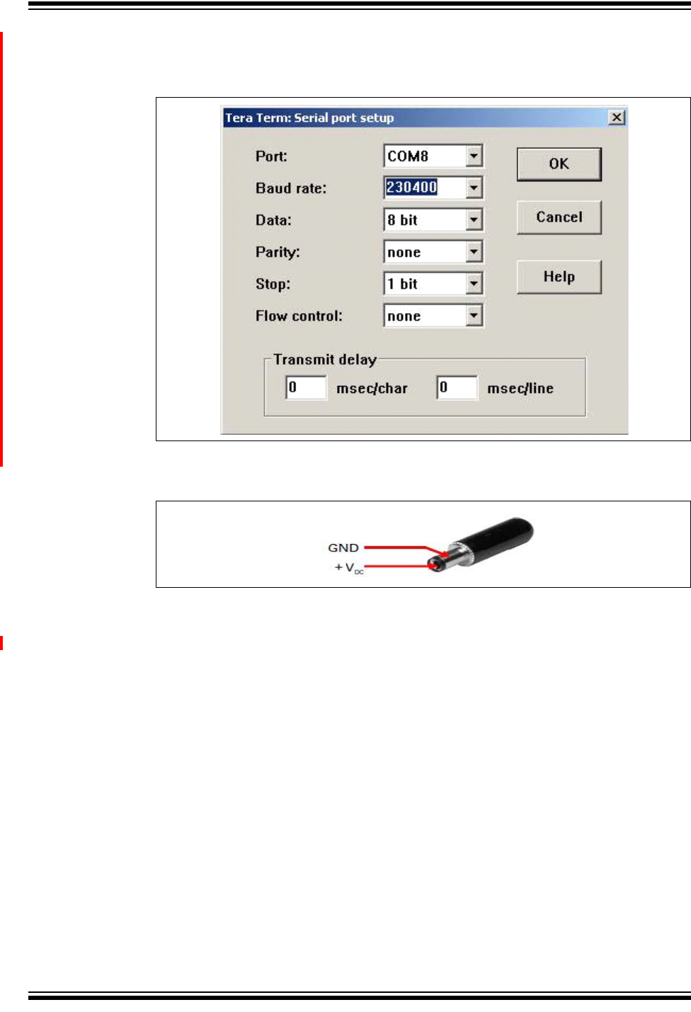
5. Configure the user console on a computer using the Serial port setup, see
Figure 2-4.
FIGURE 2-4: SERIAL PORT SETUP
6. Power on the CE2 board using the power adapter, see Figure 2-5.
FIGURE 2-5: POWER JACK CONNECTOR
7. On powering, the Bootloader software is executed. If a valid application is found,
the booting sequence will be completed and the device starts in normal mode.
8. When the application is running, continue to press <Enter> until the “
sds://”
shell command is displayed on the window, see Figure 2-6.