
User's Manual


Table Of Contents
CY920 Getting Started Guide
DS50002260B-page 18 Preliminary 2014 Microchip Technology Inc.
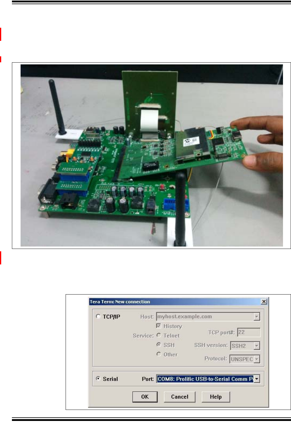
2. Connect the CY920 module and the interconnect card assembly to the connector
X2 (200 pin SODIMM connector) on the CE2 board, see Figure 1-4. Ensure that
the edge of the interconnect card must be aligned to the X2 connector and it is
inserted at an angle shown in Figure 2-2. Push the interconnect card down to
lock it on both the sides of the X2 connector.
FIGURE 2-2: INTERCONNECT CARD CONNECTED TO CE2 BOARD
3. To view shell logs, connect the USB to the serial adapter or connect the RS232
cable to the CE2 board, see Figure 1-4.
4. Use a serial terminal tool, Tera Term, for monitoring the RS232 serial data, see
Figure 2-3.
FIGURE 2-3: TERA TERM WINDOW TO SELECT COM PORT