
User's Manual


Table Of Contents
CY920 Getting Started Guide
DS50002260B-page 12 Preliminary 2014 Microchip Technology Inc.
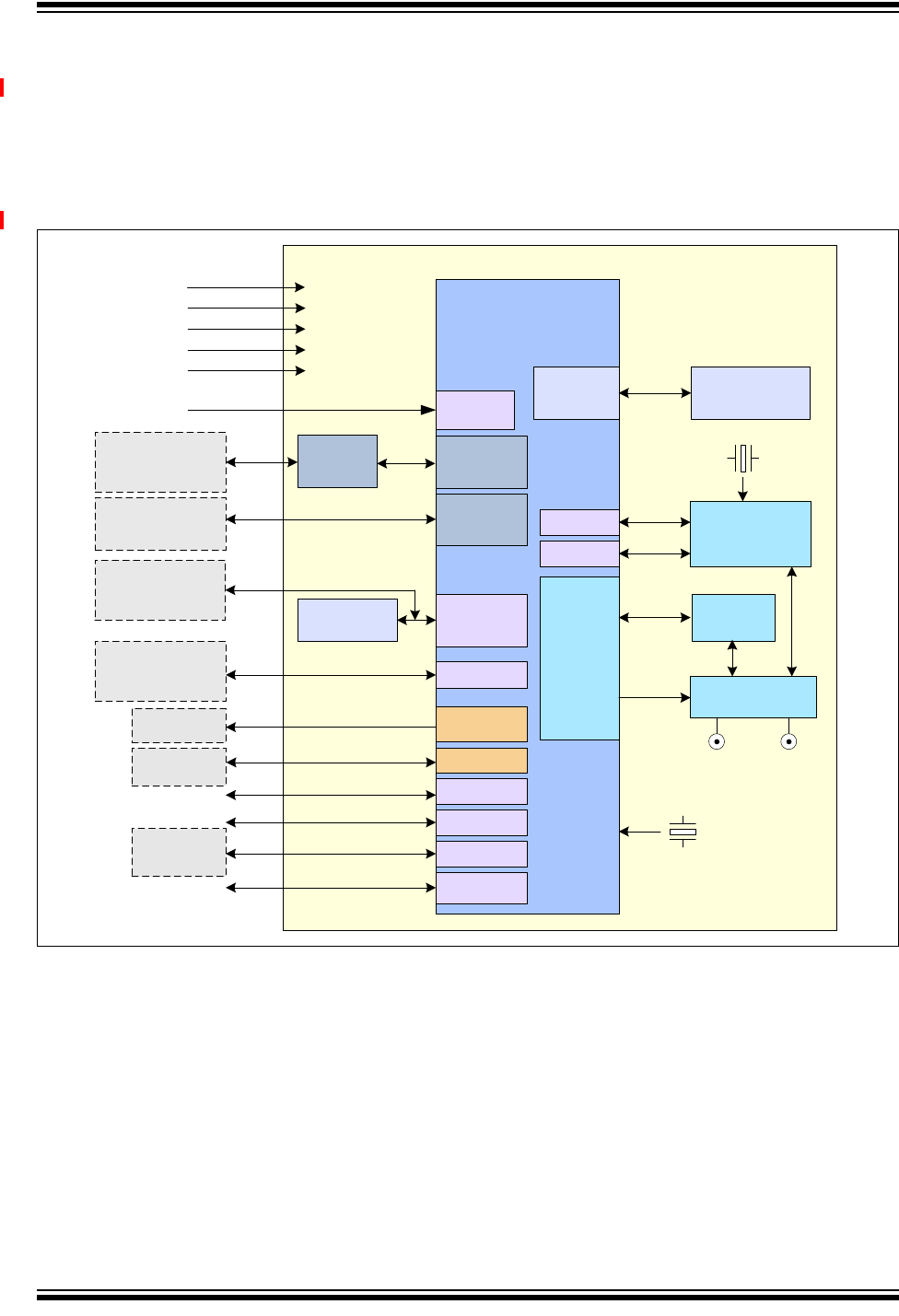
1.1 CY920 MODULE BLOCK DIAGRAM
Figure 1-1 illustrates the features of the CY920 module. The CY920 module has
various hardware configurations, known as Stock Keeping Units (SKUs). The hardware
features of the CY920 module can vary depending on the SKUs used. For more
information on SKUs used in the CY920 module, refer to the Ordering Guide section in
the “CY920 Network Media Module Data Sheet” (DS60001270).
FIGURE 1-1: CY920 NETWORK MEDIA MODULE BLOCK DIAGRAM
Ethernet
PHY
DM920 SoC
DDR2 SDRAM
64 MByte
DDR2
Controller
USB 2.0
OTG
GPIO
40.000 MHz
Serial Flash
16 MByte
2.4/5 GHz
FEM
802.11
a/b/g/n
Ethernet
Controller
UART 1
3.3V RTC
CY920 Network Media Module
1.25V
WiFi/BT
Antenna
Socket
1.8V
SPI 1
I
2
C
JTAG
RST
Reset In
AV Ports
SPI 0
Wi-Fi
Antenna
Socket
2.5V
I
2
S, S/PDIF
Bluetooth
Baseband and
RF
UART 0
GPIO
3.3V
HD Ports
HD Data
Apple
Coprocessor
Optional External
Serial Flash
Host
Controller
RJ-45
+
Transformer
USB
Type-A/Lightning
HDMI Tx
Audio A/D,
D/A
10/100
Mbps
Debug Port
Antenna Switch
26.000 MHz