
User Manual


BM62/64
Preliminary
2017 Microchip Technology Inc.
DS60001403C-Page 9
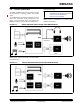
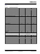
Table 1-2 provides the pin description of the BM62
module.
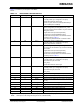
TABLE 1-2: BM62 MODULE PIN DESCRIPTION
Pin No
Pin Type
Pin Name
Description
1
I/O
P0_0
Configurable control or indication pin
(Internally pulled-up, if configured as an input)
• Slide switch detector, active-high
• UART TX_IND, active-low (used by Bluetooth sys-
tem to wakeup the host MCU)
2
I
EAN
External address bus negative
System configuration pin along with the P2_0 and
P2_4 pins, used to set the module in any one of the fol-
lowing three modes:
• Application mode (for normal operation)
• Test mode (to change EEPROM values)
• Write Flash mode (to load a new firmware into the
module), refer to Table 5-1
Flash: Must be pulled-down with 4.7 kOhm to GND
3
I/O
P3_0
Configurable control or indication pin
(Internally pulled-up, if configured as an input)
Auxiliary input detector, active-low
4
I/O
P2_0
System configuration pin along with P2_4 and EAN
pins used to set the module in any one of the following
three modes:
• Application mode (for normal operation)
• Test mode (to change EEPROM values)
• Write Flash mode (to load a new firmware into the
module), refer to Table 5-1
5
I/O
P1_5
Configurable control or indication pin
(Internally pulled-up, if configured as an input)
• NFC detection pin, active-low
• Out_Ind_1
• Slide switch detector, active-high
6
I/O
P0_4
Configurable control or indication pin
(Internally pulled-up, if configured as an input)
• NFC detection pin, active-low
• Out_Ind_1
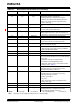
7
O
SPKR
Right-channel, analog headphone output
8
O
AOHPM
Headphone common mode output/sense input
9
O
SPKL
Left-channel, analog headphone output
10
P
VDDA
Analog reference voltage. Do not connect, for internal
use only
11
I
MIC1_P
MIC1 mono differential analog positive input
12
I
MIC1_N
MIC1 mono differential analog negative input
13
P
MIC1_BIAS
Electric microphone biasing voltage
14
I
AIR
Right-channel, single-ended analog input
15
I
AIL
Left-channel, single-ended analog input
16
I
RST_N
System Reset (active-low)
Legend: I= Input pin O= Output pin I/O= Input/Output pin P= Power pin
Note: All I/O pins can be configured using the UI tool, a Windows utility.