
User Manual


BM62/64
Preliminary
DS60001403C-Page 52
2017 Microchip Technology Inc.
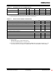
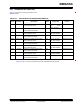
8.2 Timing specifications
Figure 8-1 and Figure 8-2 illustrate the timing diagram
.
of the BM62/64 module in I
2
S and PCM modes.
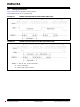
FIGURE 8-1: TIMING DIAGRAM FOR I
2
S MODES (MASTER/SLAVE)
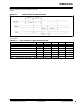
FIGURE 8-2: TIMING DIAGRAM FOR PCM MODES (MASTER/SLAVE)
Note 1: f
s
: 8,16, 32, 44.1, 48, 88.2 and 96 kHz.
2: SCLK0: 64*f
s
/256*f
s
.
3: Word Length: 16-bit and 24-bit.