
User Manual


BM62/64
Preliminary
2017 Microchip Technology Inc.
DS60001403C-Page 29
5.4
External Configuration and
Programming
The BM62/64 module can be configured by using an
external configuration tool (EEPROM tool) and the firm-
ware is programmed by using a programming tool
(Flash tool).
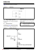
Figure 5-10 illustrates the configuration and firmware
programming interface on the BM62 module. It is
recommended to include a header pin on the main PCB
for development.
FIGURE 5-10: EXTERNAL PROGRAMMING HEADER CONNECTIONS
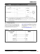
Configuration and firmware programming modes are
entered according to the system configuration I/O pins.
Table 5-1 provides the system configuration settings.
The P2_0, P2_4 and EAN pins have internal pull up.
TABLE 5-1: SYSTEM CONFIGURATION I/O PIN SETTINGS
Pins
Operating Mode
P2_0
P2_4
EAN
High
High
Low (Flash), High (ROM)
APP mode (Normal operation)
Low
High
Low (Flash), High (ROM)
Test mode (Write EEPROM)
Low
Low
High
Write Flash (BM62 only)
Note: The EEPROM and Flash tools are avail-
able for download from the Microchip web
site at: www.microchip.com/BM62 and
www.microchip.com/BM64.