
User Manual


BM62/64
Preliminary
2017 Microchip Technology Inc.
DS60001403C-Page 27
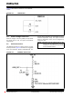
FIGURE 5-7: TIMING SEQUENCE OF POWER DROP PROTECTION
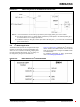
5.2 I
2
S Mode Application
The BM64 module provides an I
2
S digital audio output
interface to connect with an external codec/DSP. It pro-
vides 8, 16, 44.1, 48, 88.2, and 96 kHz sampling rates
for 16-bit and 24-bit data formats. The I
2
S setting can
be configured by using the UI and DSP tools.
Figure 5-8 and Figure 5-9 illustrate the I
2
S signal con-
nection between the BM64 module and an external
DSP. Use the DSP tool to configure the BM64 module
as a Master/Slave.
For additional information on timing specifications,
refer to 8.2 “Timing specifications”.
FIGURE 5-8: BM64 MODULE IN I
2
S MASTER MODE
Note 1: It is recommended to use the battery to provide the power supply at BAT_IN in to the module.
2: If an external power source or a power adapter is utilized to provide power to the module (ADAP_IN), it
is recommended to use a voltage supervisor IC.
3: The Reset IC output pin, RST_N, must be “Open drain” with delay time ≦ 10 ms and the recommended
part is G691L293T73.