
User Manual


BM62/64
Preliminary
2017 Microchip Technology Inc.
DS60001403C-Page 21
4.0 POWER MANAGEMENT UNIT
The on-chip Power Management Unit (PMU) has two
main features: lithium-ion and lithium-polymer battery
charger, and voltage regulator. A power switch is used
to switch over the power source between the battery
and an adapter. Also, the PMU provides current to
drive two LEDs.
4.1 Charging a Battery
The BM62/64 module has a built-in battery charger,
which is optimized for lithium-ion and lithium-polymer
batteries.
The battery charger includes a current sensor for
charging control, user programmable current regula-
tion, and high accuracy voltage regulation.
The charging current parameters are configured by the
UI tool. Reviving, pre-charging, constant current and
constant voltage modes, and re-charging functions are
included. The maximum charging current is 350 mA.
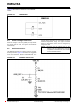
Figure 4-1 illustrates the charging curve of a battery.
FIGURE 4-1: BATTERY CHARGING CURVE
4.2 Voltage Monitoring
A 10-bit, successive approximation register ADC (SAR
ADC) provides a dedicated channel for battery voltage
level detection. The warning level can be programmed
by using the UI tool. The ADC provides a granular res-
olution to enable the external MCU to take control over
the charging process.
4.3 LED Driver
Two dedicated LED drivers control the LEDs.They pro-
vide enough sink current (16 step control and 0.35 mA
for each step), thus LEDs can be connected directly
with the BM62/64 module. The LED settings can be
configured using the UI tool.