
User Manual


BM62/64
Preliminary
2017 Microchip Technology Inc.
DS60001403C-Page 13
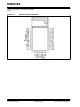
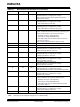
Table 1-3 provides the pin description of the BM64
Module.
TABLE 1-3: BM64 MODULE PIN DESCRIPTION
Legend: I= Input pin O= Output pin I/O= Input/Output pin P= Power pin
Note: All I/O pins can be configured using the UI tool, a Windows utility.
Pin No
Pin Type
Pin Name
Description
1
I/O
DR0
I
2
S interface: digital left/right data
2
I/O
RFS0
I
2
S interface: left/right clock
3
I/O
SCLK0
I
2
S interface: bit clock
4
I/O
DT0
I
2
S interface: digital left/right data
5
O
AOHPR
Right-channel, analog headphone output
6
O
AOHPM
Headphone common mode output/sense input
7
O
AOHPL
Left-channel, analog headphone output
8
I
MIC_N1
MIC1 mono differential analog negative input
9
I
MIC_P1
MIC1 mono differential analog positive input
10
P
MIC_BIAS
Electric microphone biasing voltage
11
I
AIR
Right-channel, single-ended analog input
12
I
AIL
Left-channel, single-ended analog input
13
I
RST_N
System Reset (active-low)
14
P
GND
Ground reference
15
I/O
P1_2
EEPROM clock SCL
16
I/O
P1_3
EEPROM data SDA
17
I/O
P0_4
Configurable control or indication pin
(Internally pulled-up, if configured as an input)
• NFC detection pin, active-low
• Out_Ind_1
18
I/O
P1_5
Configurable control or indication pin
(Internally pulled-up, if configured as an input)
• NFC detection pin, active-low
• Slide switch detector, active-high
• Out_Ind_1
• Multi-SPK Master/Slave mode control (firmware depen-
dent)
19
I
HCI_RXD
HCI-UART data input
20
O
HCI_TXD
HCI-UART data output
21
P
VDD_IO
I/O positive supply. Do not connect, for internal use only
22
P
BAT_IN
Power Supply input.
Voltage range: 3.2V to 4.2V. Source can either be a Li-Ion bat-
tery or any other power rail on the host board
23
P
ADAP_IN
5V power adapter input, used to charge the battery in the
Li-Ion battery power applications
24
P
SYS_PWR
System power output derived from ADAP_IN or BAT_IN. Do
not connect, for internal use only
25
P
AMB_DET
Analog input for ambient temperature detection
26
I
MFB
• Multi-Function Button and power-on key
• UART RX_IND, active-high (used by host MCU to
wakeup the Bluetooth system)
27
I
LED2
LED driver 2
28
I
LED1
LED driver 1