
User manual

Atmel AVR1925: XMEGA-C3 Xplained Hardware User’s Guide [APPLICATION NOTE]
42053A−AVR−02/2013
8
4. Peripherals
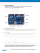
4.1 microSD card
The Atmel AVR XMEGA-C3 Xplained has a microSD card standard connector mounted. The SWA is used for detecting
the microSD card. When a misroSD card plugs in, the SWA will be pulled to GND. The connection to the MCU is shown
in Table 4-1.
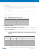
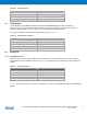
Table 4-1. microSD card connection.
Pin on XMEGA microSD card
PD1 SCK
PD3 MOSI
PD2 MISO
PE5 SS
PE4 SWA
4.2 Atmel AVR QTouch button
The XMEGA-C3 Xplained kit has one Atmel QTouch button and the connection to the Atmel AVR XMEGA is shown
in Table 4-2. The QTouch sensor, a copper fill, is located
on the second layer of the board (same as GND layer). The
sensor is shielded by the third layer (VCC layer) and therefore the sensor is not affected by any touches from the back
side of the board.
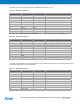
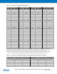
Table 4-2. QTouch button connection.
Pin on XMEGA QButton
PF4 SNS0
PF5 SNSK0
PF6 SNS1
PF7 SNSK1
4.3 Mechanical buttons
Two mechanical buttons are connected to Atmel AVR XMEGA. All buttons have external pull-ups so there is no need to
activate internal pull-ups in order to use them. When a button is pressed it will drive the I/O line to GND.
Table 4-3. Mechanical button connection.
Pin on XMEGA Silkscreen text on PCB
PF1 SW0
PF2 SW1
4.4 LEDs
There are four LEDs available on the board that can be turned on and off. Two yellow LEDs, one green LED (power
indicator LED), and one red LED (status LED). The green and red LEDs are inside the same package and therefore the
colors can be mixed to orange when both are activated. The yellow LEDs and the red LED can be activated by driving
the connected I/O line to GND. The green LED is controlled via a FET and is by default on when the board is powered.
However, this power indicator LED can also be turned off by driving the gate of the FET to GND.