
User manual

Atmel AVR1925: XMEGA-C3 Xplained Hardware User’s Guide [APPLICATION NOTE]
42053A−AVR−02/2013
6
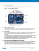
3. Connectors
The Atmel AVR XMEGA-C3 Xplained kit has four 10-pin, 100mil headers and one 6-pin 100mil header. The 6-pin
header is used for programming the Atmel AVR ATxmega384C3, and the 10-pin headers are used to access spare
analog and digital pins on the Atmel AVR XMEGA (expansion headers).
3.1 Programming headers
The XMEGA can be programmed and debugged by connecting an external programming/debugging tool to the PDI
header shown in Figure 2-1.
The grey XMEGA PDI adapt
er on the Atmel AVR JTAGICE mkII probe has to be used when connecting to the XMEGA-
C3 Xplained board.
The green standoff adaptor nr.3 (ref.A08-0254) on the Atmel AVR ONE! probe has to be used when connecting to the
XMEGA-C3 Xplained board.
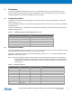
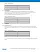
Table 3-1. XMEGA programming and debugging interface – PDI.
Pin on programming header PDI
1 DATA
2 VCC
3 -
4 -
5 CLK
6 GND
3.2 I/O expansion headers
The Atmel AVR XMEGA-C3 Xplained headers J1, J2, J3, and J4 offer access to the I/O of the microcontroller in order to
expand the board, for example by mounting a top module onto the board.
The header J1 offers digital communication interfaces like UART, TWI and SPI. Table 3-2 shows ho
w the Atmel AVR
XMEGA is connected to the header.
Note: When using TWI please note that no pull-ups are mounted on the board from the factory, so it is required to
either enable the internal pull-ups of the device or to mount the external pull-ups on the available footprints
(R200 and R201). Please refer to the assembly drawing in the design documentation for the location of
these footprints.
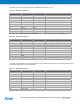
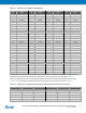
Table 3-2. Expansion header J1.
Pin on J1 Name on J1 XMEGA pin Shared with onboard functionality
1 SDA PC0 -
2 SCL PC1 -
3 RXD PC2 -
4 TXD PC3 -
5 SS PC4 -
6 MOSI PC5 -
7 MISO PC6 -
8 SCK PC7 -
9 GND - -
10 VCC_P3V3 - -