
User manual

Atmel AVR1923
7
8394B-AVR-02/12
This however will disable the JTAG interface until the connection is reestablished by,
for example soldering a bridge on the cut-strap.
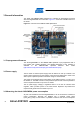
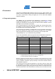
4.2 I/O expansion headers
The Atmel AVR XMEGA-A3BU Xplained headers J1, J2, J3, and J4 offer access to
the I/O of the microcontroller in order to expand the board, for example by mounting a
top module onto the board.
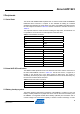
The header J1 offers digital communication interfaces like UART, TWI and SPI. Table
4-2 sho
ws how the Atmel AVR XMEGA is connected to the header.
NOTE When using TWI please note that no pull-ups are mounted on the board from the
factory, so it is required to either enable the internal pull-ups of the device or to mount
the external pull-ups on the available footprints (R200 and R201). Please refer to the
assembly drawing in the design documentation for the location of these footprints.
Table 4-2. Expansion header J1.
Pin on J1 Name on J1 XMEGA pin Shared with onboard functionality
1 SDA PC0 -
2 SCL PC1 -
3 RXD PC2 -
4 TXD PC3 -
5 SS PC4 -
6 MOSI PC5 -
7 MISO PC6 -
8 SCK PC7 -
9 GND - -
10 VCC_P3V3 - -
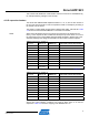
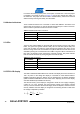
The header J2 is connected to analog ports of the XMEGA as shown in Table 4-3.
Table 4-3. Expansion header J2.
Pin on J2 Name on J2 XMEGA pin Shared with onboard functionality
1 ADC0 PB0 -
2 ADC1 PB1 -
3 ADC2 PB2 -
4 ADC3 PB3 -
5 ADC4 PA4 -
6 ADC5 PA5 -
7 ADC6 PA6 -
8 ADC7 PA7 -
9 GND - -
10 VCC_P3V3 - -
The I/O connected to the expansion header J3 is shared with on-board features as
sensors and JTAG interface. Therefore care must be taken when J3 is used for
expansions. Table 4-4 sho
ws the mapping of the XMEGA I/O to J3.