Atmel AVR1923: XMEGA-A3BU Xplained Hardware User Guide Features • • • • • • • • • Atmel® AVR® ATxmega256A3BU microcontroller FSTN LCD display with 128x32 pixels resolution Battery backup Analog sensors - Ambient light sensor - Temperature sensor Analog filter Digital I/O - Three mechanical buttons - Two user LEDs, one power LED and one status LED - Four expansion headers Touch ® - One Atmel AVR QTouch button Memory ® - Atmel AVR AT45DB642D DataFlash serial flash Footprints for external memory - Atmel AVR
Related items The following list contains links to the most relevant documents, software and tools for the Atmel AVR XMEGA-A3BU Xplained: Atmel AVR Xplained products Xplained is a series of small-sized and easy-to-use evaluation kits for 8- and 32-bit AVR microcontrollers. It consists of a series of low cost MCU boards for evaluation and demonstration of feature and capabilities of different MCU families.
Atmel AVR1923 IAR Embedded Workbench® for Atmel AVR IAR™ Embedded Workbench is a commercial C/C++ compiler that is available for 8bit AVR. There is a 30 day evaluation version as well as a 4k (code size limited) kickstart version available from their website.
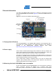
3 General information The Atmel AVR XMEGA-A3BU Xplained kit is intended to demonstrate the Atmel AVR ATxmega256A3BU microcontroller. Figure 3-1 shows the available feature on the board. Figure 3-1. Overview of the XMEGA A3BU Xplained kit. 3.1 Preprogrammed firmware The ATxmega256A3BU on the XMEGA-A3BU Xplained is pre-programmed with a boot loader and a default firmware. The detailed description of the software is available in the XMEGA-A3BU Xplained Software User Guide (http://atmel.
Atmel AVR1923 by measuring the current that is flowing into this plane. The VCC_MCU_P3V3 plane is connected via a jumper to the main power plane (VCC_P3V3) and by replacing the jumper with an amperemeter it is possible to determine the current consumption. To locate the power measurement header, please refer to Figure 3-1. WARNING Do not power the board without having the jumper or an amperemeter mounted since this can cause latch-up of the Atmel AVR ATxmega256A3BU due to current flow into the I/O pins.
4 Connectors The Atmel AVR XMEGA-A3BU Xplained kit has five 10-pins, 100mil headers. One header is used for programming the Atmel AVR ATxmega256A3BU, and the others are used to access spare analog and digital pins on the Atmel AVR XMEGA (expansion headers). 4.1 Programming headers The XMEGA can be programmed and debugged by connecting an external programming/debugging tool to the “JTAG & PDI” header shown in Figure 3-1.
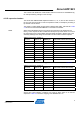
Atmel AVR1923 This however will disable the JTAG interface until the connection is reestablished by, for example soldering a bridge on the cut-strap. 4.2 I/O expansion headers The Atmel AVR XMEGA-A3BU Xplained headers J1, J2, J3, and J4 offer access to the I/O of the microcontroller in order to expand the board, for example by mounting a top module onto the board. The header J1 offers digital communication interfaces like UART, TWI and SPI.
Table 4-4. Expansion header J3. Pin on J3 Name on J3 XMEGA pin Shared with onboard functionality 1 PA0 PA0 Light sensor (1) 2 PA1 PA1 Temperature sensor (1) 3 PA2 PA2 Filter output (1) 4 PA3 PA3 Display reset 5 PB4 PB4 JTAG TMS 6 PB5 PB5 JTAG TDI 7 PB6 PB6 JTAG TCK 8 PB7 PB7 JTAG TDO 9 GND - - 10 VCC_P5V0 - - Note: 1. Can be disconnected from onboard functionality by cut-straps.
Atmel AVR1923 5 Peripherals 5.1 Serial flash The Atmel AVR XMEGA-A3BU Xplained has an external Atmel AVR AT45DB642D DataFlash device mounted. A footprint is also available for adding an industrial standard serial flash like the AT25 series from Atmel. Compatible serial flash devices for both footprints are listed in Table 5-2 and the connection to the MCU is shown in Table 5-1.
to measure the backup system power consumption a header with a mounted jumper is available. The header is shown in Figure 3-1 and is also marked with “VBAT” on the silkscreen. The jumper can also be used to simulate battery insertion and removal without actually removing the battery from the holder. 5.4 Mechanical buttons Three mechanical buttons are connected to Atmel AVR XMEGA. All buttons have external pull-ups so there is no need to activate internal pull-ups in order to use them.
Atmel AVR1923 V0: Display voltage (contrast control). Rb ⎞ ⎛ ⎜1 + ⎟ : Voltage regulator internal resistance ratio. Ra ⎠ ⎝ VREG: Internal fixed voltage supply typically 2.1V. α: Electronic volume level, 1 to 64 are possible values: ⎛ ⎝ The recommended configuration for the display is to use ⎜1 + Rb ⎞ ⎟ = 3.5 because it Ra ⎠ will center the adjustable voltage range at 6V which is the typical setting for this display. Recommended values for α are listed in Table 5-6. Table 5-6.
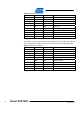
5.7 Analog I/O 5.7.1 Temperature sensor The temperature sensor circuitry consists of a serial connection of a normal and a NTC resistor. The NTC sensor is from Murata and some part details are shown in Table 5-7, more information can be obtained from the manufacturer’s website. Table 5-7. NTC characteristics.
Atmel AVR1923 Temp. [°C] NTC resistance [kΩ] Temp. [°C] NTC resistance [kΩ] Temp. [°C] NTC resistance [kΩ] Temp. [°C] NTC resistance [kΩ] -7 528.602 23 109.970 53 29.366 83 9.510 -6 499.212 24 104.852 54 28.203 84 9.185 -5 471.632 25 100.000 55 27.091 85 8.873 -4 445.772 26 95.398 56 26.028 86 8.572 -3 421.480 27 91.032 57 25.013 87 8.283 -2 398.652 28 86.889 58 24.042 88 8.006 -1 377.193 29 82.956 59 23.113 89 7.
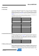
ADC input [V] Temp. [°C] ADC codes ADC input [V] Temp. [°C] ADC codes 1.055 9 1047 0.144 61 142 1.018 10 1010 0.138 62 137 0.982 11 975 0.133 63 132 0.947 12 940 0.128 64 127 0.913 13 907 0.124 65 123 0.880 14 874 0.119 66 118 0.848 15 842 0.115 67 114 0.817 16 811 0.111 68 110 0.787 17 781 0.107 69 106 0.758 18 752 0.103 70 102 0.730 19 724 0.100 71 99 0.702 20 697 0.096 72 95 0.676 21 671 0.093 73 92 0.650 22 645 0.
Atmel AVR1923 Table 5-10. Symbol description for illuminance calculation. Symbols Description ICA Calibrated sensor responsivity at 100lx. This is 50µA according to the sensor datasheet Ev Illuminance I Current through the sensor U Output voltage of the sensor circuitry that is provided to the ADC R Series resistor of the sensor circuitry. 4.
6 Code examples The example application is based on the Atmel AVR Software Framework that is included in Atmel AVR Studio 5. The AVR Software Framework can also be found as a separate package online at: http://www.atmel.com/dyn/products/tools_card.asp?tool_id=4192. For more information about the code example, see the application note Atmel AVR XMEGA-A3BU Xplained Software Users Guide: http://atmel.com/dyn/resources/prod_documents/doc8413.pdf.
Atmel AVR1923 7 Revision history To identify the revision of the Atmel AVR XMEGA-A3BU Xplained kit, locate the barcode sticker on the back side of the board. The first line on the sticker shows the product ID and the revision. For example “A09-1248/2” can be resolved to ID=A091248 and revision=2. 7.1 Revision 2 Revision 2 of the XMEGA-A3BU Xplained kit is the initially released version. This revision of the kit has the following product ID: A09-1248/2.
8 Table of contents Features ............................................................................................... 1 1 Introduction ...................................................................................... 1 2 Related items.................................................................................... 2 3 General information......................................................................... 4 3.1 Preprogrammed firmware........................................................
Atmel Corporation 2325 Orchard Parkway San Jose, CA 95131 USA Tel: (+1)(408) 441-0311 Fax: (+1)(408) 487-2600 www.atmel.com Atmel Asia Limited Unit 01-5 & 16, 19F BEA Tower, Milennium City 5 418 Kwun Tong Road Kwun Tong, Kowloon HONG KONG Tel: (+852) 2245-6100 Fax: (+852) 2722-1369 Atmel Munich GmbH Business Campus Parkring 4 D-85748 Garching b. Munich GERMANY Tel: (+49) 89-31970-0 Fax: (+49) 89-3194621 Atmel Japan 16F, Shin Osaki Kangyo Bldg.