
User manual


2
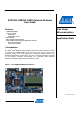
AVR1934
8413A-AVR-09/11
2 Modules and services
This demo application is available through the Atmel
®
AVR
®
Software Framework
(ASF), version 2.6.0 or later. It is available at the Atmel.com AVR Software
Framework page. The demo application is available as an example project in AVR
Studio 5. This can be accessed by clicking File → New → Example Project, and
selecting “Demo application for XMEGA-A3BU Xplained”.
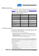
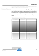
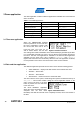
Table 2-1. List of services and modules
Module name Source file Header file
LCD panel and controller st7565r.c st7565r.h
QTouch button - touch_api.h
NTC temperature sensor ntc_sensor.c ntc_sensor.h
Ambient light sensor lightsensor.c lightsensor.h
Battery backed Real Time
Counter
rtc32.c rtc32.h
Monochrome Graphics
System (gfx_mono)
gfx_mono.c gfx_mono.h
Menu system menu.c menu.h
Calendar service calendar.c calendar.h
USB CDC service cdc.c cdc.h
2.1 LCD panel and controller
The XMEGA-A3BU Xplained board features a monochrome LCD (liquid crystal
display), which is a bundle containing an LCD controller (ST7565R) and an LCD
panel (C12832_A1Z), with white backlight.
The LCD controller offers two different interfacing modes:
1. Parallel interface mode in which display data is written by the master MCU
(XMEGA for this board) to the controller memory, eight bits at a time using eight
data lines for the transfer.
2. Serial interface mode where the master MCU produces a clock and a serial data
signal, generally known as SPI (Serial Peripheral Interface).
The latter mode is selected for this board. The advantage of using the serial interface
is that the number of pins is kept to a minimum, while the main disadvantage is that
one can only write to the display, as reading of display data is only supported when
using the parallel interface.
Five pins are needed to connect the master MCU to the LCD controller in serial
interface mode:
• Chip select, used to tell the LCD controller that it is the intended target for the
serial transmission
• Register select, used to signal whether the transmission contains data (HIGH), or
a command (LOW)
• Reset (active LOW), used to perform a hard reset of the LCD controller and the
default SPI data and clock pins