
User manual


4. Hardware User Guide
4.1. Connectors
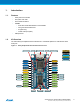
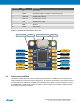
4.1.1. ATtiny104 Xplained Nano Pin-Out
The ATtiny104 Xplained Nano has a direct fan-out of the I/O pins of the device and all I/O's are accessible
at the edge connectors.
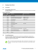
Table 4-1. Edge Connector
Edge
connector
ATtiny104
pin
Functions Shared functionality
1 V
CC
Power supply
2 PA[0] PCINT0/ADC0/AIN0/T0/CLKI/TPICLK mEDBG TPI Clock
3 PA[1] PCINT1/ADC1/AIN1/OC0B/TPIDATA mEDBG TPI Data
4 PA[2] PCINT2/RESET mEDBG Reset
5 PA[3] PCINT3/OC0A
6 PA[4] PCINT4/ICP0
7 PA[5] PCINT5/ADC2/OC0B User LED
8 PA[6] PCINT6/ADC3
9 PA[7] PCINT7
10 PB[0] PCINT8/ADC4
11 PB[1] PCINT9/INT0/ADC5/XCK0/OC0A/CLKO User button
12 PB[2] PCINT10/ADC6/TxD0/ICP0 mEDBG CDC RX
13 PB[3] PCINT11/ADC7/ACO/RxD0/T0 mEDBG CDC TX
14 GND Ground
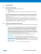
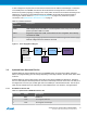
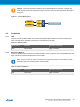
4.2. Current Measurement
The power to the target controller ATtiny104 is connected from the VREG supply to the targets VCC
supply with a 0Ω resistor as shown in the figure below. To measure the power consumption of the device,
remove the 0Ω resistor and replace it with an ammeter. The ammeter can be connected between the
VREG and VCC pads for easy measurement.
Tip: To connect the two power domains again, solder in a 0Ω resistor on the footprint or a 100-
mil header on the header footprint at the edge of the board and place a jumper between VREG
and VCC.
Atmel ATtiny104 Xplained Nano [USER GUIDE]
Atmel-42671A-ATtiny104-Xplained-Nano_User Guide-02/2016
9