
User manual

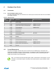

Pin number Name Description
4 NC No Connect
5 VREG Regulated voltage or VUSB if no regulator present.
6 UART RX mEDBG UART RX line
7 UART TX mEDBG UART TX line
8 CLK mEDBG clock output
9 GND Ground
10 VUSB USB voltage
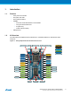
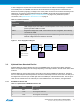
Figure 3-2. Xplained Nano Standard Pin-Out for TPI
RESET
TPI DATA
TPI CLK
NC
VREG
VUSB
GND
CLK OUT
CDC TX
CDC RX
VCC GND
Micro USB ConnectormEDBGPower disconnect Status LED
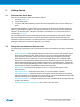
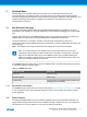
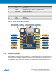
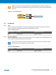
3.4. Disconnecting mEDBG
The target controller ATtiny104 can be completely separated from the mEDBG, but this requires some
small modifications to the board using a soldering iron. By removing the resistors in the sections shown in
the figure below, the mEDBG is completely disconnected from the target controller. If desired to connect
the mEDBG again, solder in 0Ω resistors or solder in 100-mil headers on the header footprints and use
wire-straps to connect the interfaces.
Atmel ATtiny104 Xplained Nano [USER GUIDE]
Atmel-42671A-ATtiny104-Xplained-Nano_User Guide-02/2016
7