
Datasheet


753
SAM4S Series [DATASHEET]
11100F–ATARM–29-Jan-14
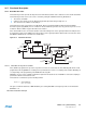
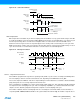
Figure 36-4. Fractional Baud Rate Generator
36.7.1.3 Baud Rate in Synchronous Mode or SPI Mode
If the USART is programmed to operate in synchronous mode, the selected clock is simply divided by the field CD in the
US_BRGR.
In synchronous mode, if the external clock is selected (USCLKS = 3), the clock is provided directly by the signal on the
USART SCK pin. No division is active. The value written in US_BRGR has no effect. The external clock frequency must
be at least 3 times lower than the system clock. In synchronous mode master (USCLKS = 0 or 1, CLK0 set to 1), the
receive part limits the SCK maximum frequency toMCK/3 in USART mode, or MCK/6 in SPI mode.
When either the external clock SCK or the internal clock divided (MCK/DIV) is selected, the value programmed in CD
must be even if the user has to ensure a 50:50 mark/space ratio on the SCK pin. If the internal clock MCK is selected, the
baud rate generator ensures a 50:50 duty cycle on the SCK pin, even if the value programmed in CD is odd.
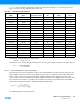
36.7.1.4 Baud Rate in ISO 7816 Mode
The ISO7816 specification defines the bit rate with the following formula:
where:
B is the bit rate
Di is the bit-rate adjustment factor
Fi is the clock frequency division factor
f is the ISO7816 clock frequency (Hz)
Di is a binary value encoded on a 4-bit field, named DI, as represented in Table 36-6.
MCK/DIV
16-bit Counter
0
Baud Rate
Clock
CD
CD
Sampling
Divider
0
1
>1
Sampling
Clock
Reserved
MCK
SCK
USCLKS
OVER
SCK
SYNC
SYNC
USCLKS = 3
1
0
2
3
0
1
0
1
FIDI
Glitch-free
Logic
Modulus
Control
FP
FP
BaudRate
SelectedClock
CD
--------------------------------------
=
B
Di
Fi
------
f×=
Table 36-6. Binary and Decimal Values for Di
DI field 0001 0010 0011 0100 0101 0110 1000 1001
Di (decimal)1 2 4 8 163212 20