
User manual


Evaluation Kit Hardware
SAM4S-EK2 User Guide 4-6
11176A–ATARM–24-Sep-12
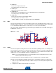
4.3.7.1 RS232
SAM4S-EK2 connects the USART1 bus (including TXD, RXD, RTS, CTS handshake signal controls and
EN command) to the DB9 male connector J5 through the RS232 Transceiver MN5.
Figure 4-6. USART Evaluation Kit Hardware
4.3.7.2 RS485
As noticed above, the USART1 is shared with the RS485 port, connected to the transceiver MN4, con-
nected to the 3-point connector J4. The design includes selectable jumpers for RS485 bus termination
resistors selection (JP10, JP11, JP12).
Figure 4-7. RS485
4.3.8 Display Interface
The SAM4S-EK2 carries a TFT Transmissive LCD module with touch panel, FTM280C34D. Its inte-
grated driver IC is ILI9325. The LCD display area is 2.8 inches diagonally measured, with a native
resolution of 240 x 320 dots.
DG ND
DG ND
+3V3
J5
5
4
3
2
1
9
8
7
6
10
11
FG ND
PA25
DG ND
MN5
ADM3312EARU
C1 +
6
C1 -
20
C2 +
2
C2 -
4
C3 +
24
C3 -
22
VCC
3
V+
1
V-
21
GND
23
SD
19
EN
5
T1 IN
7
T1 OUT
18
R1 IN
15
R1 OUT
10
T2 IN
8
T2 OUT
17
R2 IN
14
R2 OUT
11
T3 IN
9
T3 OUT
16
R3 IN
13
R3 OUT
12
PA24
C3 4
100nF
PA21_232
C3 1
4.7uF
C3 5
100nF
R3 2
47K
PA22
C3 7
100nF
USART
C3 3
100nF
R3 7 47K
PA23
C3 6
100nF
C3 2
100nF
+3V3
R3 1 0R
R3 3 0R
R3 4 0R
R3 5 0R
R3 6 0R
R3 8 0R
+3V3
PA25
PA21_485
R2 3
10K
R2 5 0R
R3 0
TB D
DNP
R2 4
TB D
DNP
+3V3
R2 6 0R
R2 7 0R
R2 8 0R
FG ND
R2 9
120R
MN4
ADM3485ARZ
RO
1
RE
2
DE
3
DI
4
VCC
8
GND
5
A
6
B
7
JP 11
Header2
JP 12
Header2
C3 0
100nF
JP 10
Header2
+3V3
DG ND
DG ND
PA22
RS 485
+3V3
PA24
J4
1
2
3
JP 28
Header2 n m
DNP