
Datasheet


1033
42023E–SAM–07/2013
ATSAM4L8/L4/L2
Dedicated Low Power Waveform, Contrast Control, Extended Interrupt Mode, ASCII Character
Mapping, automated modes... are defined to offload the CPU, reduce interrupts and reduce
power consumption.
To reduce hardware design complexity, the module includes integrated LCD buffers, an inte-
grated power supply voltage.
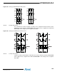
39.3 Block Diagram
Figure 39-2. LCDCA Block Diagram
39.4 I/O Lines Description
39.5 Product Dependencies
In order to use this module, other parts of the system must be configured correctly, as described
below.
LCDCA
Analog
Switch
Array
Shadow
Display
Memory
Display
Memory
Timing
LCD Power
Supply
Automated
Modes
APB Interface
SEGx
COMy
VLCD
BIASH
BIASL
CAPLCAPH
IRQBPM
CLK32
Table 39-1. I/O Lines Description
Pin Name Pin Description Type
SEGx Segment terminal x Analog
COMy Common terminal y Analog
VLCD Bias voltage Analog
BIAS1 Bias voltage (= 1/3 V
LCD
)Analog
BIAS2 Bias voltage (= 2/3 V
LCD
)Analog
CAPL High voltage end of flying capacitor Analog
CAPH Low voltage end of flying capacitor Analog