
Instructions


ATmega328P Xplained Mini User Guide [USER GUIDE]
42287A-MCU-05/2014
13
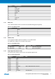
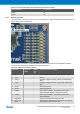
Pin Name Typical µC
signal
Typical
grid
pin
Extension signal description
11 TWI_SDA PC4/SDA M6 to
Q12
Data line for two wire interface.
12 TWI_SCL PC5/SCL M9 to
R12
Clock line for two wire interface.
13 USART_RX PD0/RXD L6 to
A12
USART Input Pin from extension board, remove R107 if
used.
14 USART_TX PD1/TXD L9 to
B12
USART Output Pin to extension board, remove R108 if
used.
15 SPI_SS_A PB2/SS K6 to
K5.5
Slave select for Serial peripheral interface.
16 SPI_MOSI PB3/MOSI K9 to
K10
Master out slave in line of Serial peripheral interface.
17 SPI_MISO PB4/MISO J6 to
J5.5
Master in slave out line of Serial peripheral interface.
18 SPI_SCK PB5/SCK J9 to
J10
Clock for Serial peripheral interface.
19 GND I6 to
GND
Ground.
20 VCC I9 to
VCC
Power for extension board.
A number of Xplained PRO Extensions can be found at http://www.atmel.com/products/microcontrollers/avr/
xplainedpro.
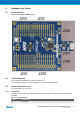
Using Pin 11 to 20 enables connection of the 10pin connector used on the RZ600 wireless modules and the
10pin Xplained sensor modules.
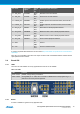
2.4 Board GUI
2.4.1 LEDs
There are one LED available for use by application SW and one for the mEDBG.
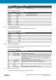
Table 2-13. LEDs
LED Function
D100 - Green mEDBG, will light during enumeration.
D200 - Yellow ATmega328P pin 17 - PB5, also connected to mEDBG SCK for ISP programming, in 3-
state when not used by the ATmega32U4.
.
2.4.2 Button
A button is available for general use by application SW.