
Instructions


ATmega328P Xplained Mini User Guide [USER GUIDE]
42287A-MCU-05/2014
11
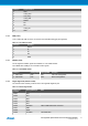
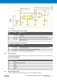
Table 2-8. J300 Board External Power Selection
J300
pin
Signal Description
1 VCC_VBUS VBUS Pin of USB Connector via fuse F100, by default connected to VCC_P5V0
via R300.
2 VCC_P5V0 Input voltage (4.3 to 16V) for the fixed-output voltage regulator (U300).
3 VCC_VIN Alternative power source for the board (4.3 to 16V), study U300 data sheet for
detail requirements.
Table 2-9. J301 Board Power Supply Selection
J301
pin
Signal Description
1 VCC_P5V0 Board external power source as selected by J300, by default connected to
VCC_BOARD via R301.
2 VCC_BOARD Power supply for ATmega32U4 and ATmega328P.
3 VCC_P3V3 Board 3.3V power supply from U300.
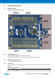
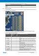
2.3.7 Target SPI (J204)
The J204 header enable direct connection to ISP for programming of the ATmega328P or to use the SPI bus to
connect external equipment.
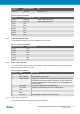
Table 2-10. J204 SPI Header
J204 pin Function
1 MISO
2 VCC target (ATmega328P)
3 SCK
4 MOSI
5 RESET
6 GND
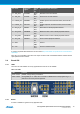
2.3.8 Additional Target Signals
Signals not available in any of the headers or connectors are available in column 5.