
Data Sheet


69
ATmega48A/PA/88A/PA/168A/PA/328/P [DATASHEET]
Atmel-8271H-AVR- ATmega-Datasheet_08/2014
12.5 Register Description
12.5.1 Moving Interrupts Between Application and Boot Space, ATmega88A/88PA, ATmega168A/168PA and
ATmega328/328P
The MCU Control Register controls the placement of the Interrupt Vector table.
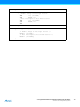
MCUCR – MCU Control Register
Note: 1. BODS and BODSE only available for picoPower devices ATmega48PA/88PA/168PA/328P
• Bit 1 – IVSEL: Interrupt Vector Select
When the IVSEL bit is cleared (zero), the Interrupt Vectors are placed at the start of the Flash memory. When
this bit is set (one), the Interrupt Vectors are moved to the beginning of the Boot Loader section of the Flash.
The actual address of the start of the Boot Flash Section is determined by the BOOTSZ Fuses. Refer to the
section ”Boot Loader Support – Read-While-Write Self-Programming” on page 264 for details. To avoid
unintentional changes of Interrupt Vector tables, a special write procedure must be followed to change the
IVSEL bit:
a. Write the Interrupt Vector Change Enable (IVCE) bit to one.
1. Within four cycles, write the desired value to IVSEL while writing a zero to IVCE.
Interrupts will automatically be disabled while this sequence is executed. Interrupts are disabled in the cycle
IVCE is set, and they remain disabled until after the instruction following the write to IVSEL. If IVSEL is not
written, interrupts remain disabled for four cycles. The I-bit in the Status Register is unaffected by the automatic
disabling.
Note: If Interrupt Vectors are placed in the Boot Loader section and Boot Lock bit BLB02 is programmed, interrupts are
disabled while executing from the Application section. If Interrupt Vectors are placed in the Application section and
Boot Lock bit BLB12 is programed, interrupts are disabled while executing from the Boot Loader section. Refer to
the section ”Boot Loader Support – Read-While-Write Self-Programming” on page 264 for details on Boot Lock bits.
• Bit 0 – IVCE: Interrupt Vector Change Enable
The IVCE bit must be written to logic one to enable change of the IVSEL bit. IVCE is cleared by hardware four
cycles after it is written or when IVSEL is written. Setting the IVCE bit will disable interrupts, as explained in the
IVSEL description above. See Code Example below.
Bit 76 5 43210
0x35 (0x55)
– BODS
(1)
BODSE
(1)
PUD – – IVSEL IVCE MCUCR
Read/Write R R/W R/W R/W R R R/W R/W
Initial Value00 0 00000