
Data Sheet

34
ATmega48A/PA/88A/PA/168A/PA/328/P [DATASHEET]
Atmel-8271H-AVR- ATmega-Datasheet_08/2014
Note: 1. This option should only be used if frequency stability at start-up is not important for the application
9.6 Calibrated Internal RC Oscillator
By default, the Internal RC Oscillator provides an approximate 8.0MHz clock. Though voltage and temperature
dependent, this clock can be very accurately calibrated by the user. See Table 29-14 on page 309 for more
details. The device is shipped with the CKDIV8 Fuse programmed. See ”System Clock Prescaler” on page 36
for more details.
This clock may be selected as the system clock by programming the CKSEL Fuses as shown in Table 9-11. If
selected, it will operate with no external components. During reset, hardware loads the pre-programmed
calibration value into the OSCCAL Register and thereby automatically calibrates the RC Oscillator. The
accuracy of this calibration is shown as Factory calibration in Table 29-14 on page 309.
By changing the OSCCAL register from SW, see ”OSCCAL – Oscillator Calibration Register” on page 38, it is
possible to get a higher calibration accuracy than by using the factory calibration. The accuracy of this
calibration is shown as User calibration in Table 29-14 on page 309.
When this Oscillator is used as the chip clock, the Watchdog Oscillator will still be used for the Watchdog Timer
and for the Reset Time-out. For more information on the pre-programmed calibration value, see the section
”Calibration Byte” on page 285.
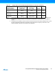
Notes: 1. The device is shipped with this option selected.
2. If 8MHz frequency exceeds the specification of the device (depends on V
CC
), the CKDIV8 Fuse can be
programmed in order to divide the internal frequency by 8.
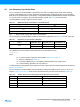
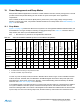
When this Oscillator is selected, start-up times are determined by the SUT Fuses as shown in Table 9-12.
Note: 1. If the RSTDISBL fuse is programmed, this start-up time will be increased to
14CK + 4.1ms to ensure programming mode can be entered.
2.
The device is shipped with this option selected.
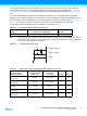
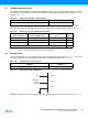
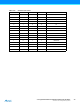
Table 9-10. Start-up Times for the Low-frequency Crystal Oscillator Clock Selection
CKSEL3...
0
Start-up Time from
Power-down and Power-save Recommended Usage
0100
(1)
1K CK
0101 32K CK Stable frequency at start-up
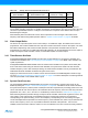
Table 9-11. Internal Calibrated RC Oscillator Operating Modes
Frequency Range
(2)
(MHz) CKSEL3...0
7.3 - 8.1 0010
(1)
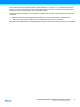
Table 9-12. Start-up times for the internal calibrated RC Oscillator clock selection
Power Conditions
Start-up Time from Power-
down and Power-save
Additional Delay from
Reset (V
CC
= 5.0V) SUT1...0
BOD enabled 6 CK 14CK
(1)
00
Fast rising power 6 CK 14CK + 4.1ms 01
Slowly rising power 6 CK 14CK + 65ms
(2)
10
Reserved 11