
Data Sheet


288
ATmega48A/PA/88A/PA/168A/PA/328/P [DATASHEET]
Atmel-8271H-AVR- ATmega-Datasheet_08/2014
28.7 Parallel Programming
28.7.1 Enter Programming Mode
The following algorithm puts the device in Parallel (High-voltage) Programming mode:
1. Set Prog_enable pins listed in Table 28-14 on page 288 to “0000”, RESET pin to 0V and V
CC
to 0V.
2. Apply 4.5 - 5.5V between V
CC
and GND.
Ensure that V
CC
reaches at least 1.8V within the next 20 µs.
3. Wait 20 - 60 µs, and apply 11.5 - 12.5V to RESET.
4. Keep the Prog_enable pins unchanged for at least 10µs after the High-voltage has been applied to ensure
the Prog_enable Signature has been latched.
5. Wait at least 300 µs before giving any parallel programming commands.
6. Exit Programming mode by power the device down or by bringing RESET pin to 0V.
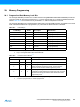
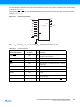
Table 28-14. Pin Values Used to Enter Programming Mode
Pin Symbol Value
PAGEL Prog_enable[3] 0
XA1 Prog_enable[2] 0
XA0 Prog_enable[1] 0
BS1 Prog_enable[0] 0
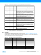
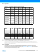
Table 28-15. XA1 and XA0 Coding
XA1 XA0 Action when XTAL1 is Pulsed
0 0 Load Flash or EEPROM Address (High or low address byte determined by BS1).
0 1 Load Data (High or Low data byte for Flash determined by BS1).
1 0 Load Command
1 1 No Action, Idle
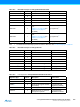
Table 28-16. Command Byte Bit Coding
Command Byte Command Executed
1000 0000 Chip Erase
0100 0000 Write Fuse bits
0010 0000 Write Lock bits
0001 0000 Write Flash
0001 0001 Write EEPROM
0000 1000 Read Signature Bytes and Calibration byte
0000 0100 Read Fuse and Lock bits
0000 0010 Read Flash
0000 0011 Read EEPROM