
Data Sheet


281
ATmega48A/PA/88A/PA/168A/PA/328/P [DATASHEET]
Atmel-8271H-AVR- ATmega-Datasheet_08/2014
28. Memory Programming
28.1 Program And Data Memory Lock Bits
The ATmega 48A/48PA provides two Lock bits and the ATmega88A/88PA/168A/168PA/328/328Pprovides six
Lock bits. These can be left unprogrammed (“1”) or can be programmed (“0”) to obtain the additional features
listed in Table 28-2. The Lock bits can only be erased to “1” with the Chip Erase command.
The ATmega 48A/48PA has no separate Boot Loader section, and the SPM instruction is enabled for the whole
Flash if the SELFPRGEN fuse is programmed (“0”). Otherwise the SPM instruction is disabled.
Notes: 1. “1” means unprogrammed, “0” means programmed.
2. Only on ATmega88A/88PA/168A/168PA/328/328P.
Notes: 1. Program the Fuse bits and Boot Lock bits before programming the LB1 and LB2.
2. “1” means unprogrammed, “0” means programmed
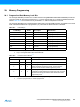
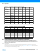
Table 28-1. Lock Bit Byte
(1)
Lock Bit Byte Bit No Description Default Value
7 – 1 (unprogrammed)
6 – 1 (unprogrammed)
BLB12
(2)
5 Boot Lock bit 1 (unprogrammed)
BLB11
(2)
4 Boot Lock bit 1 (unprogrammed)
BLB02
(2)
3 Boot Lock bit 1 (unprogrammed)
BLB01
(2)
2 Boot Lock bit 1 (unprogrammed)
LB2 1 Lock bit 1 (unprogrammed)
LB1 0 Lock bit 1 (unprogrammed)
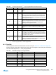
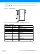
Table 28-2. Lock Bit Protection Modes
(1)(2)
Memory Lock Bits Protection Type
LB Mode LB2 LB1
1 1 1 No memory lock features enabled.
210
Further programming of the Flash and EEPROM is disabled in
Parallel and Serial Programming mode. The Fuse bits are
locked in both Serial and Parallel Programming mode.
(1)
300
Further programming and verification of the Flash and EEPROM
is disabled in Parallel and Serial Programming mode. The Boot
Lock bits and Fuse bits are locked in both Serial and Parallel
Programming mode.
(1)