
Data Sheet


272
ATmega48A/PA/88A/PA/168A/PA/328/P [DATASHEET]
Atmel-8271H-AVR- ATmega-Datasheet_08/2014
or if no LPM instruction is executed within three CPU cycles or no SPM instruction is executed within four CPU
cycles. When BLBSET and SPMEN are cleared, LPM will work as described in the Instruction set Manual.
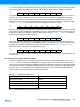
The algorithm for reading the Fuse Low byte is similar to the one described above for reading the Lock bits. To
read the Fuse Low byte, load the Z-pointer with 0x0000 and set the BLBSET and SPMEN bits in SPMCSR.
When an LPM instruction is executed within three cycles after the BLBSET and SPMEN bits are set in the
SPMCSR, the value of the Fuse Low byte (FLB) will be loaded in the destination register as shown below. Refer
to Table 28-5 on page 283 for a detailed description and mapping of the Fuse Low byte.
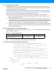
Similarly, when reading the Fuse High byte, load 0x0003 in the Z-pointer. When an LPM instruction is executed
within three cycles after the BLBSET and SPMEN bits are set in the SPMCSR, the value of the Fuse High byte
(FHB) will be loaded in the destination register as shown below. Refer to Table 28-7 on page 283 for detailed
description and mapping of the Fuse High byte.
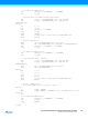
When reading the Extended Fuse byte, load 0x0002 in the Z-pointer. When an LPM instruction is executed
within three cycles after the BLBSET and SPMEN bits are set in the SPMCSR, the value of the Extended Fuse
byte (EFB) will be loaded in the destination register as shown below. Refer to Table 28-5 on page 283 for
detailed description and mapping of the Extended Fuse byte.
Fuse and Lock bits that are programmed, will be read as zero. Fuse and Lock bits that are unprogrammed, will
be read as one.
27.8.10 Reading the Signature Row from Software
To read the Signature Row from software, load the Z-pointer with the signature byte address given in Table 27-
5 on page 272 and set the SIGRD and SPMEN bits in SPMCSR. When an LPM instruction is executed within
three CPU cycles after the SIGRD and SPMEN bits are set in SPMCSR, the signature byte value will be loaded
in the destination register. The SIGRD and SPMEN bits will auto-clear upon completion of reading the Signature
Row Lock bits or if no LPM instruction is executed within three CPU cycles. When SIGRD and SPMEN are
cleared, LPM will work as described in the Instruction set Manual.
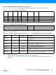
Note: All other addresses are reserved for future use.
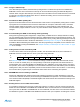
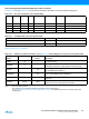
Bit 76543210
Rd – – BLB12 BLB11 BLB02 BLB01 LB2 LB1
Bit 76543210
Rd FLB7 FLB6 FLB5 FLB4 FLB3 FLB2 FLB1 FLB0
Bit 76543210
Rd FHB7 FHB6 FHB5 FHB4 FHB3 FHB2 FHB1 FHB0
Bit 76543210
Rd – – – – EFB3 EFB2 EFB1 EFB0
Table 27-5. Signature Row Addressing
Signature Byte Z-Pointer Address
Device Signature Byte 1 0x0000
Device Signature Byte 2 0x0002
Device Signature Byte 3 0x0004
RC Oscillator Calibration Byte 0x0001