
Data Sheet

251
ATmega48A/PA/88A/PA/168A/PA/328/P [DATASHEET]
Atmel-8271H-AVR- ATmega-Datasheet_08/2014
• Bit 4 – ADIF: ADC Interrupt Flag
This bit is set when an ADC conversion completes and the Data Registers are updated. The ADC Conversion
Complete Interrupt is executed if the ADIE bit and the I-bit in SREG are set. ADIF is cleared by hardware when
executing the corresponding interrupt handling vector. Alternatively, ADIF is cleared by writing a logical one to
the flag. Beware that if doing a Read-Modify-Write on ADCSRA, a pending interrupt can be disabled. This also
applies if the SBI and CBI instructions are used.
• Bit 3 – ADIE: ADC Interrupt Enable
When this bit is written to one and the I-bit in SREG is set, the ADC Conversion Complete Interrupt is activated.
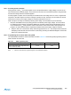
• Bits 2:0 – ADPS[2:0]: ADC Prescaler Select Bits
These bits determine the division factor between the system clock frequency and the input clock to the ADC.
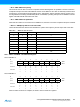
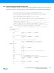
24.9.3 ADCL and ADCH – The ADC Data Register
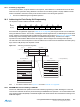
24.9.3.1 ADLAR = 0
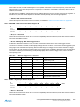
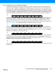
24.9.3.2 ADLAR = 1
When an ADC conversion is complete, the result is found in these two registers.
Table 24-5. ADC Prescaler Selections
ADPS2 ADPS1 ADPS0 Division Factor
000 2
001 2
010 4
011 8
100 16
101 32
110 64
111 128
Bit 151413121110 9 8
(0x79) – – – – – – ADC9 ADC8 ADCH
(0x78) ADC7 ADC6 ADC5 ADC4 ADC3 ADC2 ADC1 ADC0 ADCL
76543210
Read/Write RRRRRRRR
RRRRRRRR
Initial Value00000000
00000000
Bit 151413121110 9 8
(0x79) ADC9 ADC8 ADC7 ADC6 ADC5 ADC4 ADC3 ADC2 ADCH
(0x78) ADC1 ADC0 – – – – – – ADCL
76543210
Read/Write R R R R R R R R
RRRRRRRR
Initial Value 0 0 0 0 0 0 0 0
00000000