
Data Sheet


249
ATmega48A/PA/88A/PA/168A/PA/328/P [DATASHEET]
Atmel-8271H-AVR- ATmega-Datasheet_08/2014
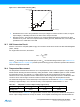
temperature measurement can be calibrated in the application software. The software calibration requires that a
calibration value is measured and stored in a register or EEPROM for each chip, as a part of the production test.
The software calibration can be done utilizing the formula:
T = { [(ADCH << 8) | ADCL] - T
OS
} / k
where ADCn are the ADC data registers, k is a fixed coefficient and T
OS
is the temperature sensor offset value
determined and stored into EEPROM as a part of the production test.
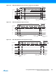
24.9 Register Description
24.9.1 ADMUX – ADC Multiplexer Selection Register
• Bit 7:6 – REFS[1:0]: Reference Selection Bits
These bits select the voltage reference for the ADC, as shown in Table 24-3. If these bits are changed during a
conversion, the change will not go in effect until this conversion is complete (ADIF in ADCSRA is set). The
internal voltage reference options may not be used if an external reference voltage is being applied to the AREF
pin.
•
Bit 5 – ADLAR: ADC Left Adjust Result
The ADLAR bit affects the presentation of the ADC conversion result in the ADC Data Register. Write one to
ADLAR to left adjust the result. Otherwise, the result is right adjusted. Changing the ADLAR bit will affect the
ADC Data Register immediately, regardless of any ongoing conversions. For a complete description of this bit,
see ”ADCL and ADCH – The ADC Data Register” on page 251.
• Bit 4 – Reserved
This bit is an unused bit in the ATmega48A/PA/88A/PA/168A/PA/328/P, and will always read as zero.
• Bits 3:0 – MUX[3:0]: Analog Channel Selection Bits
The value of these bits selects which analog inputs are connected to the ADC. See Table 24-4 for details.
If
these bits are changed during a conversion, the change will not go in effect until this conversion is complete
(ADIF in ADCSRA is set).
Bit 76543210
(0x7C) REFS1 REFS0 ADLAR – MUX3 MUX2 MUX1 MUX0 ADMUX
Read/Write R/W R/W R/W R R/W R/W R/W R/W
Initial Value00000000
Table 24-3. Voltage Reference Selections for ADC
REFS1 REFS0 Voltage Reference Selection
0 0 AREF, Internal V
ref
turned off
01
AV
CC
with external capacitor at AREF pin
10Reserved
1 1 Internal 1.1V Voltage Reference with external capacitor at AREF pin