
Data Sheet

117
ATmega48A/PA/88A/PA/168A/PA/328/P [DATASHEET]
Atmel-8271H-AVR- ATmega-Datasheet_08/2014
Note: 1. See ”About Code Examples” on page 8.
For I/O Registers located in extended I/O map, “IN”, “OUT”, “SBIS”, “SBIC”, “CBI”, and “SBI” instructions must
be replaced with instructions that allow access to extended I/O. Typically “LDS” and “STS” combined with
“SBRS”, “SBRC”, “SBR”, and “CBR”.
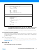
The assembly code example requires that the r17:r16 register pair contains the value to be written to TCNT1.
16.3.1 Reusing the Temporary High Byte Register
If writing to more than one 16-bit register where the high byte is the same for all registers written, then the high
byte only needs to be written once. However, note that the same rule of atomic operation described previously
also applies in this case.
16.4 Timer/Counter Clock Sources
The Timer/Counter can be clocked by an internal or an external clock source. The clock source is selected by
the Clock Select logic which is controlled by the Clock Select (CS12:0) bits located in the Timer/Counter control
Register B (TCCR1B). For details on clock sources and prescaler, see ”Timer/Counter0 and Timer/Counter1
Prescalers” on page 139.
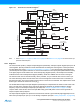
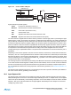
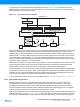
16.5 Counter Unit
The main part of the 16-bit Timer/Counter is the programmable 16-bit bi-directional counter unit. Figure 16-2
shows a block diagram of the counter and its surroundings.
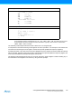
Assembly Code Example
(1)
TIM16_WriteTCNT1:
; Save global interrupt flag
in r18,SREG
; Disable interrupts
cli
; Set TCNT1 to r17:r16
out TCNT1H,r17
out TCNT1L,r16
; Restore global interrupt flag
out SREG,r18
ret
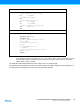
C Code Example
(1)
void TIM16_WriteTCNT1( unsigned int i )
{
unsigned char sreg;
unsigned int i;
/* Save global interrupt flag */
sreg = SREG;
/* Disable interrupts */
_CLI();
/* Set TCNT1 to i */
TCNT1 = i;
/* Restore global interrupt flag */
SREG = sreg;
}