
User manual

8
AVR364
8377B-AVR-11/11
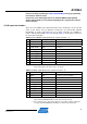
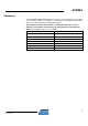
Table 4-4. Atmel MEGA-1284P Xplained I/O expansion header – J3.
Pin J3 ATmega1284P pin Shared with onboard functionality
1 GPIO0 PB0 SW0, LED0
2 GPIO1 PB1 SW1, LED2
3 GPIO2 PB2 SW2, LED3
4 GPIO3 PB3 LED1
5 GPIO4 PD4 J4 (SPI SS1), DataFlash (SPI SS1)
6 GPIO5
(1)
PD5 Filter input
7 GPIO6 PC4 JTAG(TDO)
8 GPIO7 PC5 JTAG(TDI)
9 GND - -
10 VCC_P5V0
(2)
- -
Notes: 1. This signal can be disconnected from the filter input by cutting the cut-strap
marked FILTER INPUT in the SENSORS & FILTER section on the bottom side
of the board.
2. Pin 10 of header J3 is connected to the USB voltage (VCC_P5V0).
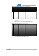
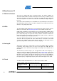
Table 4-5. MEGA-1284P Xplained I/O expansion header – J4.
Pin J4 ATmega1284P pin Shared with onboard functionality
1 TWI SDA PC1 Header J1, board controller
2 TWI SCL PC0 Header J1, board controller
3 USART RXD1 PD2 Board controller
4 USART TXD1 PD3 Board controller
5 SPI SS1 PD4 Header J3 (GPIO4), DataFlash
6 SPI MOSI
(1)
PB5 Header J1, DataFlash, board controller
7 SPI MISO
(1)
PB6 Header J1, DataFlash, board controller
8 SPI SCK
(1)
PB7 Header J1, DataFlash, board controller
9 GND - -
10 VCC_P3V3 - -
Note: 1. These signals can be disconnected from the board controller by cutting the cut-
straps marked SPI on the bottom side of the board.