
User manual

AVR364
7
8377B-AVR-11/11
Please note that programming the Atmel AT32UC3B1256 using a programming
tool will erase the boot loader.
Please refer to the Atmel application note, AVR370: MEGA-1284P Xplained
Getting Started Guide, for more details regarding how to program the onboard
microcontrollers.
4.2 I/O expansion headers
There are four available I/O expansion headers in the kit. Because of the low pin
count on the device, the I/O expansion header pins are shared with onboard
functionality. If “clean” expansion ports are needed, cut-straps are available to
remove onboard functionality. Table 4-2 throu
gh Table 4-5 show what is shared on
the respective header pins.
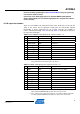
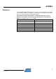
Table 4-2. Atmel MEGA-1284P Xplained I/O expansion header – J1.
Pin J1 ATmega1284P pin Shared with onboard functionality
1 TWI SDA PC1 Header J4, board controller
2 TWI SCL PC0 Header J4, board controller
3 USART RXD0 PD0 Header J4
4 USART TXD0 PD1 Header J4
5 SPI SS
(1)
PB4 Board controller
6 SPI MOSI
(1)
PB5 Header J4, DataFlash, board controller
7 SPI MISO
(1)
PB6 Header J4, DataFlash, board controller
8 SPI SCK
(1)
PB7 Header J4, DataFlash, board controller
9 GND - -
10 VCC_P3V3 - -
Note: 1. These signals can be disconnected from the board controller by cutting the cut-
straps marked SPI on the bottom side of the board.
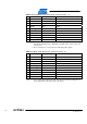
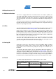
Table 4-3. MEGA-1284P Xplained I/O expansion header – J2.
Pin J2 ATmega1284P pin Shared with onboard functionality
1 ADC0
(1)
PA0 Possible to connect to AREF
2 ADC1 PA1 -
3 ADC2 PA2 -
4 ADC3 PA3 -
5 ADC4 PA4 -
6 ADC5
(2)
PA5 Filter output
7 ADC6
(2)
PA6 Light sensor
8 ADC7
(2)
PA7 NTC sensor
9 GND - -
10 VCC_ANA_P3V3 - -
Notes: 1. AREF with 100nF capacitor to GND can be connected to ADC0 by shorting two
pads marked EXTERNAL AREF on the bottom side of the board.
2. These signals can be disconnected from the sensor/filter output by cutting the
cut-straps marked SENSORS & FILTER on the bottom side of the board.