
User manual

6
AVR364
8377B-AVR-11/11
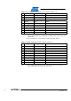
4 Connectors
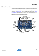
The Atmel MEGA-1284P Xplained kit has five 10-pin, 100mil headers. Two headers
have a fixed communication interface (J1 and J4). One header has analog
functionality (J2), and the last header (J3) has general purpose digital I/O.
The 90° angled header is the Atmel ATmega1284P
JTAG programming and
debugging header.
For the location of the respective headers, refer to Figure 3-1.
4.1 Programming headers
The ATmega1284P can be programmed and debugged by connecting an external
programming/debugging tool to the JTAG pin header. The pin header has a standard
JTAG programmer pin-out (refer to online help in the Atmel AVR Studio), ena
bling
tools like the Atmel AVR JTAGICE mkII or the Atmel AVR ONE! to be
connected
directly to the header.
The grey, female, 10-pin header on the AVR JTAGICE mkII mu
st be used when
connecting to the kit. A scoring in the board is made to fit the orientation tab on
the header.
A standoff adapter (nr. 1) is needed when using the AVR ONE!
Pin 1 on the JTAG head
er is at the top right corner. This is rotated 180°
compared to the other headers (J1, J2, J3, and J4).
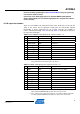
Table 4-1. MEGA-1284P Xplained programming and debugging interface – JTAG.
Pin JTAG
(1)
1 TCK
2 GND
3 TDO
4 VCC
5 TMS
6 nSRST
7 -
8 -
9 TDI
10 GND
Note: 1. Standard pin-out for the AVR JTAGICE mkII and other Atmel programming tools
The Atmel AT32UC3B1256 can be programmed through its boot loader. The boot
loader is evoked by shorting the two holes marked BOOTLOADER BOARD
CONTROLLER on the bottom side of the board before applying power to the board.
The two holes have 100mil spacing, enabling the user to solder in a two-pin header
and use a jumper to easily enter the boot loader. Programming is performed through
the boot loader programmer target in the Atmel AVR Studio.
Alternatively, the AT32UC3B1256
can also be programmed by connecting a
programming tool, such as the AVR JTAGICE mkII, to the
10 holes marked JTAG
BOARD CONTROLLER on the bottom side of the board. The holes have 100mil
spacing, letting the user solder in a 10-pin header to program the board controller.