
User manual

AVR364
5
8377B-AVR-11/11
3.2 Power supply
The kit is powered via the USB connector, which presents two options for powering it:
Either connect the kit to a PC through a USB cable or to a 5V USB power supply
(AC/DC adapter).
The 5V is regulated to 3.3V with an LDO regulator, which provides power to the entire
board. The Atmel ATmega1284P is p
owered by 3.3V, but if 1.8V operation is desired,
some modifications to the board are needed. This includes replacing the regulator
with one that delivers a 1.8V output and rerouting the power to the device (see
schematic for an explanation). As some of the other ICs on the Atmel MEGA-1284P
Xplained require 3.3V to operate correctly, these devices have to be removed.
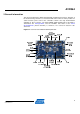
3.3 Measuring the ATmega1284P power consumption
As part of an ATmega1284Pevaluation, it can be of interest to measure its power
consumption. The two-pin power measurement header is the only connection
between the VCC_P3V3 common power plane and the VCC_MCU_P3V3 power
plane. By replacing the jumper with an ammeter, it is possible to determine the
ATmega1284P current
consumption. To locate the power measurement header,
please refer to Figure 3-1.
Do not p
ower the board without having the jumper or an ammeter mounted. If
this is done the board might be powered through an I/O pin. The result might be
erratic behavior and the device might get damaged.
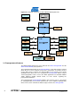
3.4 Communication through the USART-to-USB gateway
The ATmega1284P USART is connected to a USART on the Atmel AT32UC3B1256.
The ATmega1284P USA
RT is communicating at 57600 baud using one start bit, eight
data bits, one stop bit, and no parity.
When the AT32UC3B1256 device i
s enumerated (connected to a PC). the data
transmitted from the ATmega1284P i
s passed to a (virtual) COM port. This means
that it is possible to use a terminal program on a PC to receive the transmitted data.
Similarly data transmitted from the PC COM port is passed to the ATmega1284P
USART throu
gh the gateway.