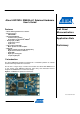
Atmel AVR1924: XMEGA-A1 Xplained Hardware User's Guide Features • Atmel® ATxmega128A1 microcontroller • External memory - 8MB SDRAM • Atmel AT32UC3B1256 - Communication gateway - Programmer for Atmel AVR® XMEGA® • Analog input (to ADC) - Temperature sensor - Light sensor • Analog output (from DAC) - Mono speaker via audio amplifier • Digital I/O - UART communication through USB gateway - Eight mechanical button switches - Eight LEDs - Eight spare analog pins - 24 spare digital pins 8-bit Atmel Microcontrol
Related items Atmel FLIP (Flexible In-system Programmer) http://www.atmel.com/dyn/products/tools_card.asp?tool_id=3886 Atmel AVR Studio® 4 (free Atmel IDE) http://www.atmel.com/dyn/products/tools_card.asp?tool_id=2725 Atmel AVR JTAGICE mkII (on-chip programming and debugging tool) http://www.atmel.com/dyn/products/tools_card.asp?tool_id=3353 Atmel AVR ONE! (on-chip programming and debugging tool) http://www.atmel.com/dyn/products/tools_card.
Atmel AVR1924 The preprogrammed Atmel AT32UC3B1256 firmware offers features such as a boot loader for self-programming and a UART-to-USB gateway. 3.2 Power supply The kit is powered via the USB connector, which leaves two options to power it: Connect the kit either to a PC through a USB cable, or to a 5V USB power supply (AC/DC adapter). 3.3 Measuring the XMEGA power consumption As part of an evaluation of the Atmel ATxmega128A1, it can be of interest to measure its power consumption.
Connectors The Atmel XMEGA-A1 Xplained kit has five 10-pin, 100mil headers. One header is used for programming the Atmel ATxmega128A1, and the others are used to access spare analog and digital pins on the XMEGA (expansion headers). 4.1 Programming headers The XMEGA can be programmed and debugged by connecting an external programming/debugging tool to the JTAG and PDI header (J201).
Atmel AVR1924 programming is performed through the FLIP plug-in in AVR Studio (which can also be started as a standalone application). FLIP (Flexible In-system Programmer) is free Atmel proprietary software that runs on Windows® 9x/Me/NT/2000/XP and Linux® x86. FLIP supports in-system programming of flash devices through RS232, USB, or CAN. Alternatively, the AT32UC3B1256 can be programmed by connecting a programming tool, such as JTAGICE mkII, to test points TP600-607.
5 Attached memories The Atmel XMEGA-A1 Xplained kit demonstrates how to use the external bus interface (EBI) module to connect a 4-bit SDRAM. An 8MB SDRAM (16Mb x 4) is attached in three-port EBI mode (PORTH, PORTK, and PORTJ).
Atmel AVR1924 6 Miscellaneous I/O 6.1 Mechanical button switches Eight mechanical button switches are connected to XMEGA PORTD(PD0:PD5) and PORTR(PR0:PR1). Internal pull-ups should be enabled to detect when the buttons are pushed, as they short the respective line to GND. NOTE Buttons share the pins with the J3 header: Pushing the buttons potentially affects communication or other functionality on these pins. 6.2 LEDs Eight yellow LEDs are connected to XMEGA PORTE.
7 Included code example The example application is based on the Atmel AVR Software Framework found online at http://asf.atmel.no. For documentation, help, and examples on the drivers used, please see the website. For more information about the included code example, see the Atmel application note “AVR1927: XMEGA-A1 Xplained Getting Started Guide”. 7.
Atmel AVR1924 8 Further code examples and drivers Several Getting-Started trainings for the Atmel XMEGA-A1 Xplained kit can be downloaded from the Atmel website. These trainings offer general introduction to XMEGA peripherals. Please refer to AVR1500 through AVR1510. Further information and drivers for XMEGA can be downloaded as application notes, also distributed from the Atmel website.
9 Known issues 9.1 Light sensor The output range of the light sensor is 0V – 3.3V. The ADC reference must therefore be high enough to match the output range of the light sensor when performing measurements. 9.2 USB test points Touching the test points of the USB data lines on the reverse side of the board while there is an ongoing communication, might interrupt the device and cause the device to stop responding. The kit must be reconnected to start working properly again. 9.
Atmel AVR1924 10 Revision history The revision of the evaluation kit can be found on the sticker on the reverse side of the PCB. 10.1 Revision 7 The Atmel XMEGA-A1 Xplained kit, revision 7, is the first released revision of the XMEGA-A1 Xplained kit. This kit replaces the Atmel Xplain evaluation kit. Information about the original Xplain evaluation kit can be found in the Atmel application note AVR1907: Xplain Hardware User’s Guide. 10.2 Revisions 1 to 6 Not released.
11 Table of contents Features ............................................................................................... 1 1 Introduction ...................................................................................... 1 2 Related items.................................................................................... 2 3 General information......................................................................... 2 3.1 Preprogrammed firmware.......................................................
Atmel Corporation 2325 Orchard Parkway San Jose, CA 95131 USA Tel: (+1)(408) 441-0311 Fax: (+1)(408) 487-2600 www.atmel.com Atmel Asia Limited Unit 01-5 & 16, 19F BEA Tower, Milennium City 5 418 Kwun Tong Road Kwun Tong, Kowloon HONG KONG Tel: (+852) 2245-6100 Fax: (+852) 2722-1369 Atmel Munich GmbH Business Campus Parkring 4 D-85748 Garching b. Munich GERMANY Tel: (+49) 89-31970-0 Fax: (+49) 89-3194621 Atmel Japan 16F, Shin Osaki Kangyo Bldg.