
User manual


-24 AVR Butterfly User Guide
4271C–AVR–04/05
Table 3-1. UART
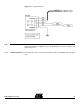
Figure 3-17. UART Connector
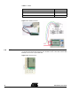
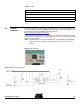
3.8 USI The AVR Butterfly has connections for the USI-interface. Figure 3-18 shows the pin-out
for the USI. Through the USI interface other modules can be connected, and the AVR
Butterfly can serve as a top-module card.
Figure 3-18. USI Connector
AVR Butterfly UART COM2
Pin 1 (RXD) Pin 3
Pin 2 (TXD) Pin 2
Pin 3 (GND) Pin 5