
User manual


-16 AVR Butterfly User Guide
4271C–AVR–04/05
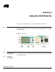
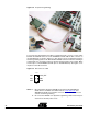
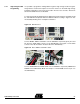
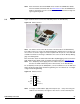
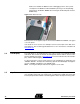
Figure 3-2. In-System Programming
To program the ATmega169 using ISP Programming mode, connect a 6-wire cable
between the ISP6PIN connector on the STK500 board and J403 the ISP connector on
the AVR Butterfly as shown in Figure 3-2. This device can be programmed using the
Serial Programming mode in the AVR Studio4 STK500 software. Instead of soldering in
a ISP-header, one can make contact just by pressing the header to the footprint. Make
sure that pin 1 on the STK500 match with pin 1 on the AVR Butterfly. See Figure 3-3 for
the pinout of the ISP Connector.
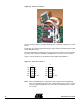
Figure 3-3. ISP Connector, J403
Notes: 1. More information about the STK500 can be found in the STK500 User
Guide, which is available at the Atmel web site, www.atmel.com
. See
STK500 User Guide for information on how to use the STK500 front-end
software for ISP Programming.
2. Do not use the AVRISP for In-System Programming, unless if the kit is pow-
ered from an external power source.
1 2
PB3
VCC_EXT
PB1 PB2
RST
GND
ISP